Ford Parts Wiki | GM Parts Wiki
Home | Search | Browse
Prev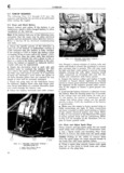
 Next
Next
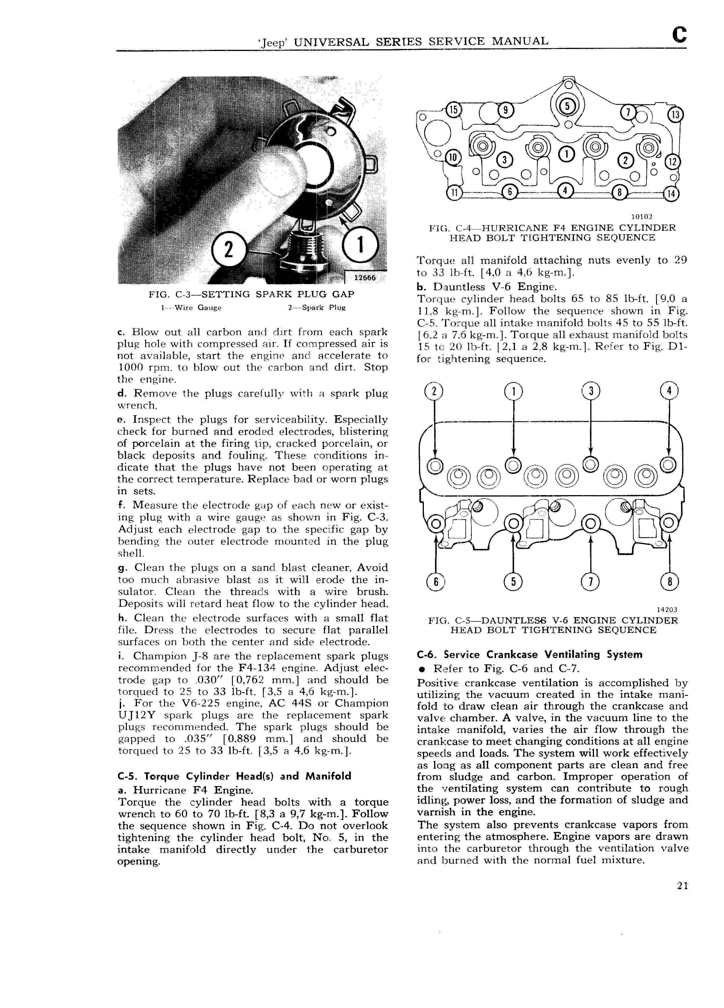
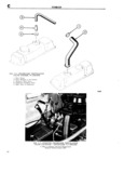
eep UEIIYERSAL SERIES MANUA I e O E V i 2 E zV ll G E v v I v jj Si e Q L O 41 L QSZE I V AV I ls K j CT E T vi i C mn J QQ G I VV EV Qi 1 lz V E i I i l O O O O N 9 0 O 2 V P A I Qi V r S E in g lil I Z1 L 1 VS 1 l 5 1 A r 10102 V E h mt 1 4 enURR1c n E F4 ENGINE cYL1ND1cR A VA QS A I I V Torque all manifold attaching nuts evenly to 29 r 1 3 n iii 8 n nS L8 ji mj tf Q yl gcm l FIG j3 SE NG G F lUG GAP retque cylinder head bolts 65 to 85 ibn 21 0 e 1 Gauge 2r a 11 8 regent Follow tue sequence snewn in rag r C 5 I or que all intake manifold bolts 45 to 55 lb ft c Blow out all carbon ancirdirt from each spark I6 v2 8 7 6 kg m Torque all exhaust mammrd brits plug hole with compressed air If compressed air is 15 O 20 lb ft i2 1 3 2y8 kg m Refer to Fig DL not available start the engine and accelerate to for rrilghtening Sequencg 1000 rpm to blow out the carbon and dirt Stop the engine V A K d Remove the plugs carefully with a spark plug l l 3 4 l wrench e Inspect the plugs for serviceabiliixy Especially e T check for burned and eroded electrodes blistering of porcelain at the firing tip cracked porcelain or black deposits and fouling These conditions in f E dicate that the plugs have not been operating at pi the correct temperature Replace bad or worn plugs in sets jji f IVIea sure the electrode gap of each new or exist T O ing plug with a wire gauge as shown in Fig C 3 drlfrlid J O J O 5 Adjust each electrode gap to the specific gap by il Ez bending the outer electrode mounted in the plug gjii Q shell g Clean the plugs on a sand blast cleaner Avoid too much abrasive blast as it will erode the in B 5 7 3 sulator Clean the threads with a wire brush Deposits will retard heat flow to the cylinder head 14203 h Clean the electrode surfaces with a small flat pK j 5 DAUNTLESS V 6 ENGIN 5 CYLIND ERl file Dress the electrodes to secure flat parallel HEAD BOLT TIGHTENING SEQUENCE surfaces on both the center and side electrode i Champion I 8 are the replacement spark plugs C 6 9l Vil Z Crahkcase Ventilating System recommended for the F4 l3 l engine Adjust elec Refer to Fig C 6 and C 7 trode gap t0 030 0 762 mm and 8l 10 ld be Positive crankcase ventilation is accomplished by lmqugl to 25 te 33 1b ft l3 5 3 4 5 kg m l utilizing the vacuum created in the intake mani Fewhe V6 225 e s M 448 Ch3mi 1 fold to draw eieen ear through the erenkeeee end UJIZY Spark Plugs GIG th YGP l G mGnt Spark valve chamber A valve in the vacuum line to the plugs 1 3 d1 The Srmk rluss Sheuld be anteike nnenlreid varies the en new tineugn the eapiwd tel 055 0889 t mgm Mi Sheuld be erenkeeeei to meet changing conditions at all engine YGYGIUGG te 25 YG 33 lb ft l 3 i 3 4 6 kg m l speeds and loads The system will work effectively as long as all component parts are clean and free C 5 Torque Cylinder Head s and Manifold from sludge and carbon Improper operation of a Huyricang F4 Errgirra the ventilating system can contribute to rough Torque the cylinder head bolts with ei torque idling power loss and the formation of sludge and wrench to 60 to 70 lb ft 8 3 a 9 7 kg rn Follow varnish m thi gm the sequence shown in Fig C 4 Do not overlook The system also prevents crankcase vapors from tightening the cylinder head bolt No 5 in the entering the atmosphere Engine vapors are drawn intake manifold directly under the carburetor into the carburetor through the ventilation valve opening and burned with the normal fuel mixture 21