Ford Parts Wiki | GM Parts Wiki
Home | Search | Browse
Prev
 Next
Next
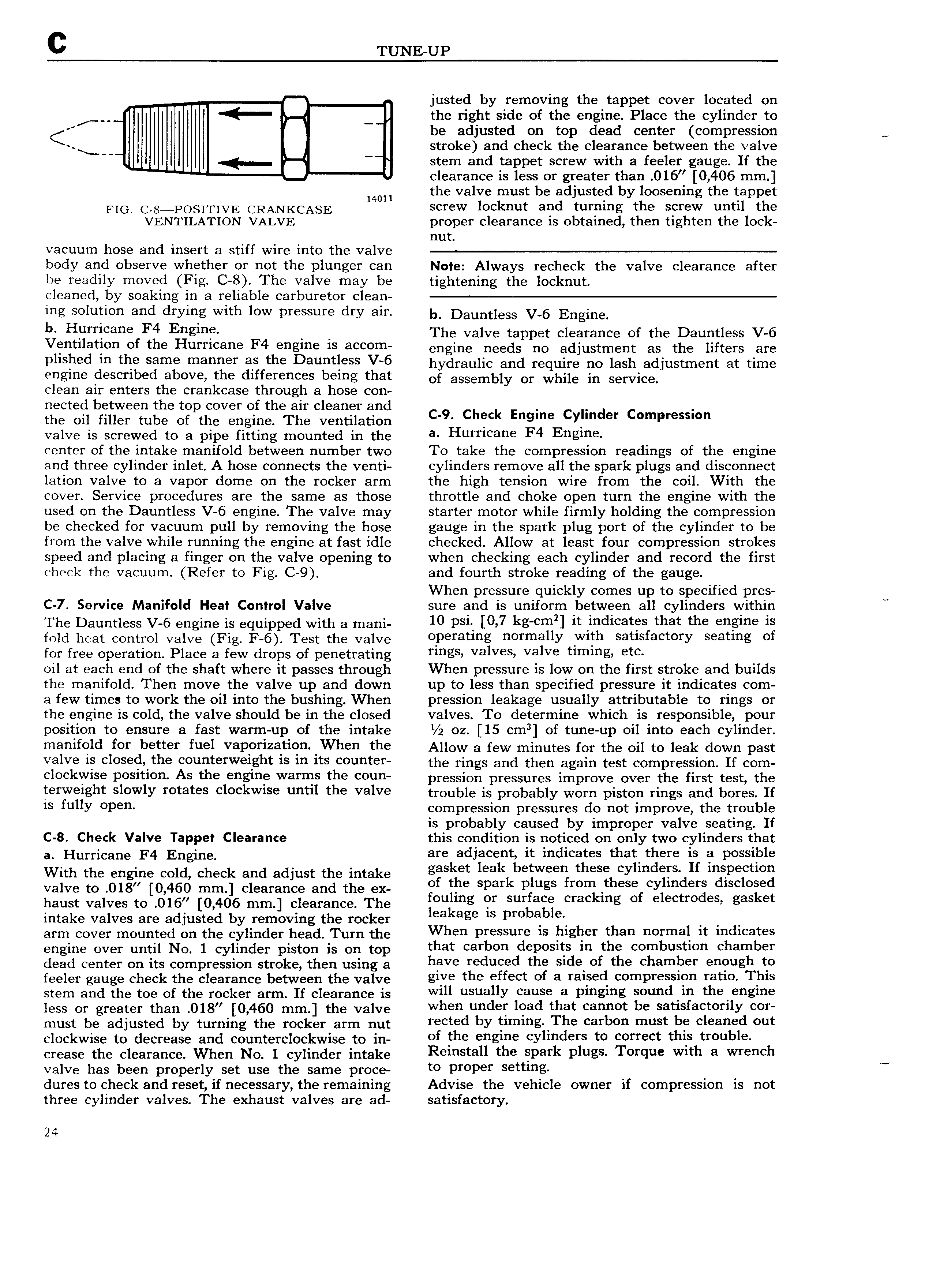
C TUNE UP justed by removing the tappet cover located on I the right side of the engine Place the cylinder to be adjusted on top dead center compression K l I stroke and check the clearance between the valve U Y I stem and tappet screw with a feeler gauge If the clearance is less or greater than O16 0 406 mm Wm the valve must be adjusted by loosening the tappet FiG C s POsiTiVE CRAINKCASE screw locknut and turning the screw until the VENTILATION VALVE proper clearance is obtained then tighten the lock nut vacuum hose and insert a stiff wire into the valve body and observe whether or not the plunger can Note Always recheck the valve clearance after be readily moved Fig C 8 The valve may be tightening the locknut cleaned by soaking in a reliable carburetor clean ing solution and drying with low pressure dry air b Dauntless V 5 Engine ll Hurrlcane F4 Englne The valve tappet clearance of the Dauntless V 6 Ventilation of the Hurricane F4 engine is accom engine needs ne adjustment as the llftets are Pllsherl ln the sarne rnanner as the Dauntless V 6 hydraulic and require no lash adjustment at time engine described above the differences being that Ot assembly or While in sei vlee clean air enters the crankcase through a hose con nected between the top cover of the air cleaner and the oil filler tube of the engine The ventilation C 9 Check Englne Cylmder C mPreSsl n valve is screwed to a pipe fitting mounted in the a Hurrlcane F4 Englne center of the intake manifold between number two To take the compression readings of the engine and three cylinder inlet A hose connects the venti cylinders remove all the spark plugs and disconnect lation valve to a vapor dome on the rocker arm the high tension wire from the coil With the cover Service procedures are the same as those throttle and choke open turn the engine with the used on the Dauntless V 6 engine The valve may starter motor while firmly holding the compression be checked for vacuum pull by removing the hose gauge in the spark plug port of the cylinder to be from the valve while running the engine at fast idle checked Allow at least four compression strokes speed and placing a finger on the valve opening to when checking each cylinder and record the first check the vacuum Refer to Fig C 9 and fourth stroke reading of the gauge When pressure quickly comes up to specified pres C 7 Service Manifold Heat Control Valve sure and is uniform between all cylinders within M The D3UHtl SS v 6 ehgihe is equipped with e mehi 10 ps 0 7 ks cmll tt i d1 tes that the gu ls fold heat control valve Fig F 6 Test the valve oPeratlng norrnallY Wltn satlsfacrorv seatlng or for free operation Place a few drops of penetrating rlngs valves valve rlnllngv etc oil at each end of the shaft where it passes through When pressure is low on the first stroke and builds the manifold Then move the valve up and down up to less than specified pressure it indicates com a few times to work the oil into the bushing When pression leakage usually attributable to rings or the engine is cold the valve should be in the closed valves To determine which is responsible pour position to ensure a fast warm up of the intake oz 15 cmg of tune up oil into each cylinder manifold for better fuel VePorfZetlon When the Allow a few minutes for the oil to leak down past valve is closed the counterweight is in its counter the rings and then again test Compression If Cem clockwise Posltlon As the englne warms the eoun pression pressures improve over the first test the terweight slowly rotates clockwise until the valve trgublg is probably wom piston l ings and bO es If is fully oPen compression pressures do not improve the trouble is probably caused by improper valve seating If C 8 Check Valve Tappet Clearance this condition is noticed on only two cylinders that a Hurric n F En ine are adjacent it indicates that there is a possible With the lehitiuel cold check and adjust the intake gasket leak between these Yll tleFs ll ltlspestlea Valve to 018 I 0 460 mm Clearance and the x of the spark plugs from rthesef cylinder disclosied haust valves to 016 0 406 mm clearance The folllmg er surface ttackmg O eleette s gas et intake valves are adjusted by removing the rocker leakage ls r r bel le arm cover mounted on the cylinder head Turn the When Pressure ls hlgher th normal lt lnulcares engine ever until Nd l eylinder piston is on top that carbon deposits in the combustion chamber dead center on its compression stroke then using a have reduced the slde or the charnher eneugn to feeler gauge check the clearance between the valve glve the effect of a ralsetl cornpresslon rant Tllls stem and the toe of the rocker arm If clearance is Wlll usuellY cause a Plnglng sound ln ths g s less Or greater than 0lg 0 450 rnrn the Valve when under load that cannot be satisfactorily cor must be adjusted by turning the rocker arm nut rected by t1IIl1 g Th carbon must be cleaned out clockwise to decrease and counterclockwise to in of the englne cYllnclers ts correct this trouble crease the e1eetehee When Ne 1 eyiihdet intake Fs st 11 thettspsrk plugs Torque wuh 3 wfs h W valve has been properly set use the same proce o Proper se lng dures to check and reset if necessary the remaining Advise the vehicle owner if compression is not three cylinder valves The exhaust valves are ad satisfactory 24