Ford Parts Wiki | GM Parts Wiki
Home | Search | Browse
Prev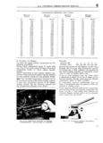
 Next
Next
c TUNE UP C I0 Distributor Service being made Recheck the gap after locking the The distributor cap should be inspected for cracks adlustnsenty carbon runners and evidence of arcing If any APPly a tnln tllrn ef carn lubrreent te the cam te of these conditions exists the cap should be re lessen nber bleek Weer pioccd ciooh any corroded high tension terminals sheuld e ee de eer tester be everleble the eer ee ty Inspect the rotor for cracks or evidence of exces Sheuld cheek trorn 2l te 25 rnlcrotarads ln the sive burning at the end of the metal strip After absence ef a tester cneck by substltutlng a new a distributor rotor has had normal use the end condenser of the rotor will become burned If burning is found Cneck Polnt contact sPrlng Pressure wnlcb Sheuld on top of the rotor it indicates the rotor is too be between 17 end 20 ounces 0 487 a 0 56 kg short and needs replacing Usually when this con Check wltn a sbrlng scale heekea on the breaker dition is found the distributor cap segment will arrn at tne contact and Pull at rlgnt angle te tne be burned on the horizontal face and the cap will breaker arm Make tne readlng Just es tne Polnts also need replacing U separate Adjust the point pressure by loosening Check rho condenser lead for broken wrrcs or the Stud heldmg the errd ef the eenteet erm Sprmg frayed insulation Clean and tighten the connec and sllde tne end ef tne sprlng ln er out es neces tions on the terminal posts Be sure the condenser sary Retrgbten tne stud and recneclr the Pressure is mounted firmly on the distributor for a good ree lew a Pressure wlll cause e g e rnlsslng et ground connectionl high speeds Too high a pressure will cause rapid Should a condenser tester be available the capacity wear ef tne canar bleek and Polnts should be checked In the absence of a tester check b Dauntjoss V 6 Engine Delco by substituting a new c0nde Ser The spark advance is fully automatic being con Exarnlne tne dretrrbuter Polnts Flg C ll lr tney trolled by built in centrifugal weights and by a snow wear Poor rnatlngr transferred rnetalr er vacuum advance system Fig C l3 The same Plttlngrtnen new ones Should be lnstalled Clean checking procedures are used as a above except the Points with a suitable Selvent end a stlrt the capacity of the condenser must be 18 to 23 brrstled brush microfarads and the contact gap should be set at Cheek the alignment of the Polnt fer a full square 016 0 406 mm Adjustment of the gap is made contact If Het correctly allgned bend tne statlon by rotating the socket head adjustment screw with ary contact bracket slightly to provide alignment 3 1 8 3 86 mm Allen Wrench Fig C 14 a Hurricane F4 Engine Prestolite The contact spring pressure must be 19 to 23 ozs The contact gap of the distributor point on the l0 s38 a 0 6 52 gr 1 end the cant dwell angle 1S Hurricane F4 engine should be set at 020 0 508 30 with distributor Vacuum lrne drseenneeted mm measured with a wire gauge Adjustment of The preferred method of adjusting cam dwell re the gap is accomplished by loosening the lock qu1reS turnmg of the adjusting screw until the screw and turning adjusting eccentric screw Fig SD C1f1C dwell angle is obtained as measured by a C 12 until correct gap is secured Be sure that the dwell angle meter Refer to Par C 17 To adjust fiber block on the breaker arm is resting on the the cam dwell by an alternate method turn the highest point on the cam while the adjustment is adjusting Screw 1n clockwise until the engine 2 r rrrr l r ii i Ii i i li t FIG C 12 PRESTOLITE DISTRIEUTCR HURRICANE F4 ENGINE v I Condenser v l lo 2 L r e z l 2 r 4 ubricatmg Wick yf j i r 3 Brr aker Cam 4 B c aker Arm Pivo l M 2 5 Distributor Cap lgotation Bo Firing Order Els i v 0 Distrihutor Points M v rv 4 7 Adjustment Lock Screw a j t 87Adjusting Eccentric Screw 9 v 9 O1ler ft l 10 Primary Wire 6 i 6 I IVL Q 14248 26