Ford Parts Wiki | GM Parts Wiki
Home | Search | Browse
Prev

 Next
Next
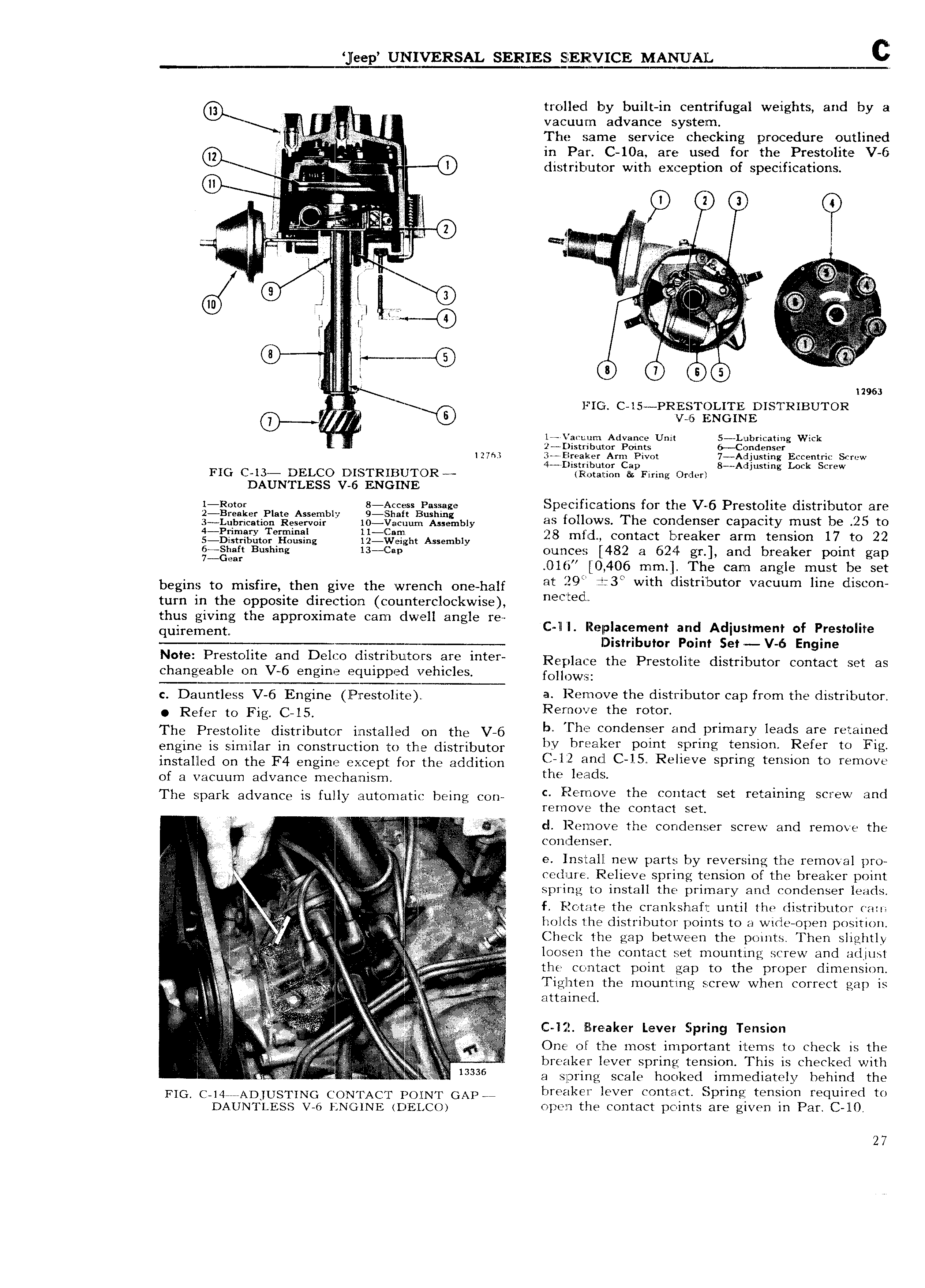
e ep UNIVERSAL SERIES SPEFICVICE MANUAL trollecl b built in centrifugal weights and by a A Y l vacuurzn advance system I The same service checking procedure outlined V i g E in Par C 10a are used for the Prestolite V 6 T Q I QD iistrib u tor with exception of specifications A i A A 2 1 3 4 i A T r J i A Al g I V r A AA g c C T if C AA A T i m I ll i I l v i ifYll I r i L i l 1 A Ji i A l s i i Cl a 7 i 12961 i I FIG C l5 PRZELST LITE DISTRIBUTOR V 6 ENGINE H E l r Vacunrn Advance Unit 5 Lubricating Wick 2 Distributor Points 6 Condenser 1276 3 Elrealcer Arm Pivot 7 Adjusting Eccentric Screw t I istribut or Cap 8 Adjusting Lock Screw FIC C l3 DELCO D IlSTRII3I T OR Rotation Bn Firing Order DAUN I LESS V 6 ENGINE m l 0 Pl A bl 3 t C ss 3p dngn Specifications for the V 6 Prestolite distributor are 2 1l iiiii igtinliiaisnsnziiliixil T vn ininuii 1 l liibiy db follows The condenser capacity must be zE to 1 J V I 5 D Q tjgmr ng 12 g ht Assembly 28 midi contact breaker arm tension 17 to 22 gi nn Bushing 13 Csp ounces 482 a 624 gr and breaker po1n t gap mr U 1 i 0 406 mm The cam angle must be set begins to inisiins then give the wrench dndiinii 1 9 i3 Wh i St b t f V m hm l 1S turn in the opposite direction counterclockwise n d thus givin the a roximate cam dwell an le re A I tg pp 1 g C ll I llelplacement and Adlustment of Prestolite E ioasmbuinr Point sei v is Engine N Preiltohte and DSICO d S t b MC rS im mt Replace the Prestolite distributor contact set as changeable on V 6 engine equipped vehicles MHOWS c Dauntlgss V 6 Engine P y st jt a Remove the distributor cap from the distributor Refer to Fig C 15 Remove the rotor The Prestolite distributor installed on the V 6 rh COnd n d l m3TY l adS are m1 d engine is similar in construction to the distributor ly Tbrwlfer pomt Y rmg t Sl0 Refer lo F1 installed dn the F4 engine except ini the addition 2 Ml 15 Rsllsive Sams t S t m v of a vacuum advance mechanism mg l dS The Spark advance is fully aumnmtic being COW c lE 2e rrio the contact set retaining screw and remove t e contact set T I A cl Remove the condenser screw and remove the i A VV E aanaav condenser ii c iii l ll E EiEE EE ii ii 2 ii A if i ii A lnmlll W parts by r v r i s the r m v 1 vm i i E i 2 cednre Relieve s rin tension of the breaker noint E ig 5 U E p g I N L llg i i i ii i i i l4 I ilplsllpl VVV C M spring to install the primary and condenser leads I V j i f Efotute the crankshaft until the rlistfibutof Till C V EV A holds the distributor points to a wide open position azv T i EV if T iiA E Check the gap between the points Then slightly i A A A A loosen the contact set mounting screw and adjust A A A V A A YY i ii ii thc Contact point gap to the proper dimension l tt E EEEi 2 iiill A A A iA W T l t the m s Screw Wim t sev is A i i A Fi i r V A 3 i EEE tt i l ii i A l i VV EEE zzv iii C li 2E hre aker Lever Spring Tension l c AA 2 1 i i 5 A E A One of the most im ortant items to check is the i j 5 5 A s i ti 5 A ai p i T i 2 A c i i A l reaker lever spring tension This is checked with i i 3A i f 3336 3 ggpring scale hooked immediately behind the FIG C l4i iADJUSTTNG CONTACT POINT GAP i breaker lever contact Spring tension required to DAAUNTLESS V 6 l QN4 NE 4DEj co cipcrn the contact points are given in Par C l0 27

 Next
Next