Ford Parts Wiki | GM Parts Wiki
Home | Search | Browse
Prev

 Next
Next
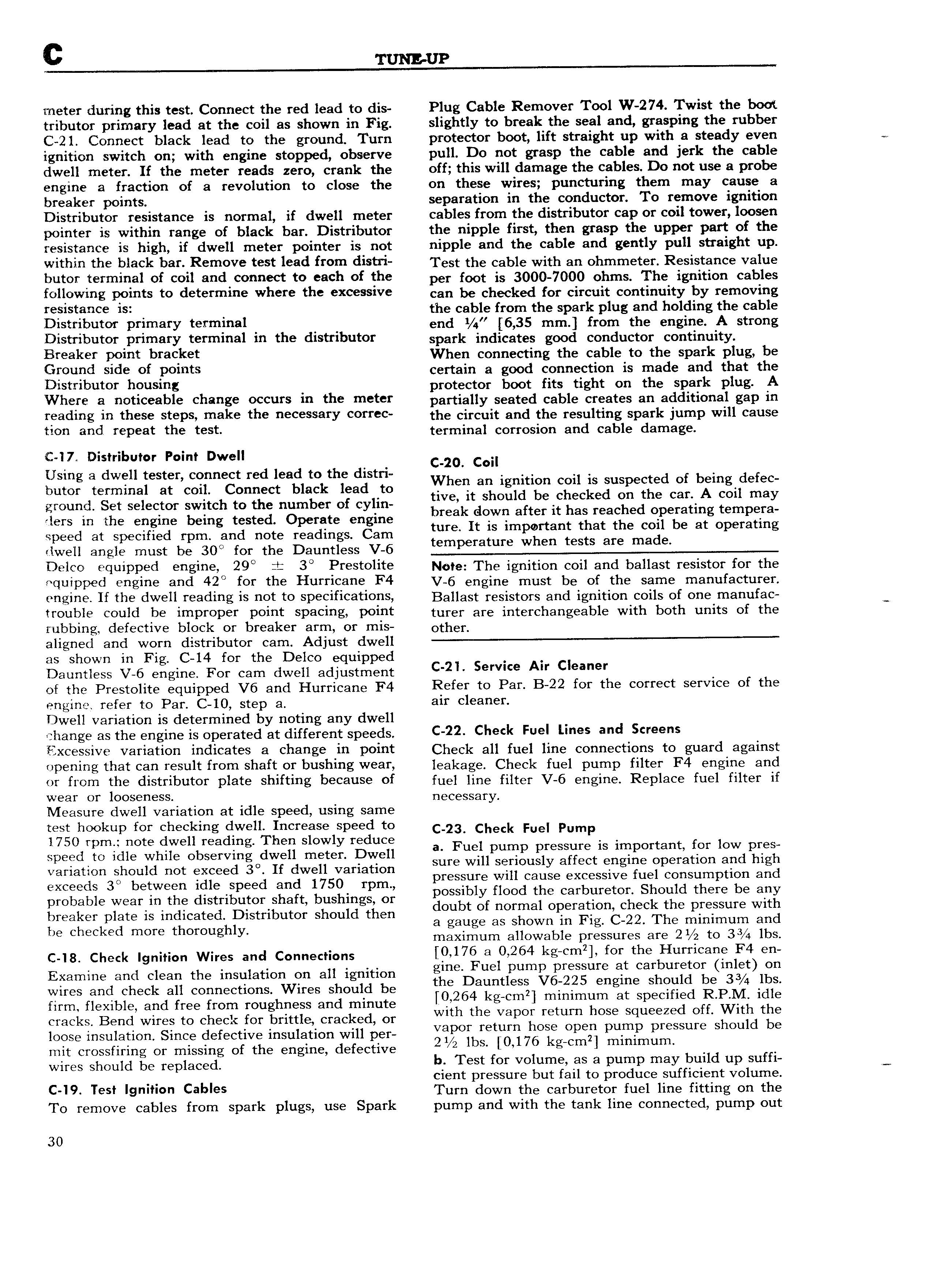
c TUNEUP meter during this test Connect the red lead to dis Plug Cable Remover Tool W 2 74 Twist the boot tributor primary lead at the coil as shown in Fig slightly to break the seal and grasping the rubber C 2l Connect black lead to the ground Turn protector boot lift straight up with a steady even ignition switch on with engine stopped observe pull Do not grasp the cable and jerk the cable dwell meter If the meter reads zero crank the off this will damage the cables Do not use a probe engine a fraction of a revolution to close the on these wires puncturing them may cause a breaker points separation in the conductor To remove ignition Distributor resistance is normal if dwell meter cables from the distributor cap or coil tower loosen pointer is within range of black bar Distributor the nipple first then grasp the upper part of the resistance is high if dwell meter pointer is not nipple and the cable and gently pull straight up within the black bor Remove test lead from diem Test the cable with an ohmmeter Resistance value butor terminal of coil and connect to each of the per fggt is 3 7 olims The ignition cables following points to determine where the excessive can be checked for eirouit continuity by removing resistance 1s the cable from the spark plug and holding the cable Disrriburcr Primary terminal end i 4 6 35 mm from the engine A strong Distributor primary t I I l 3l lll th dlSl I lb 1tOl spark jndicgtgg good conductor c0ntinuity Breaker point bracket When connecting the cable to the spark plug be Ground side of points certain a good connection is made and that the Distributor housing protector boot fits tight on the spark plug A Where ri ootioeoble choose Occurs io the meter partially seated cable creates an additional gap in reading Jn these stlips make the necessary correc the circuit and the resulting spark jump will cause tion an repeat t e test terminal corrosion and cable damage 247 Distributor Point Dwell 020 coil Using a dwell tester connect red lead to the distri Wh 1 d b d f butor terminal at coil Connect black lead to ml an lgigtlgn CEI Ls suspecge O Xmgl e ec ground Set selector switch to the number of cylin tw it shim ec E On t 6 car cm may 1ers in the en ine b in t sted 0 rate gn ing break duwii aftef if has feoohed operating tempora g g pe g It is im rtant that the coil be at 0 eratm speed at specified rpm and note readings Cam mn PO p g clwell angle must be 300 for the Dauntless V 6 temperature when tests are mad8 Delco equipped engine 29 2 3 Prestolite Neve The ignition coil and ballast resistor for the equipped engine and 420 for the Hurricane F4 V 6 engine must be of the same manufacturer r ri iric ii me dwell readme is not to SP iri 6 i0 S Ballast resistors and ignition coils of one manufac g trouble could be improper point spacing point turer are interchangeable with both units of the rubbing defective block or breaker arm or mis otl ier aligned and worn distributor cam Adjust dwell as shown in Fig C l4 for the Delco equipped Dauntless V 6 engine For cam dwell adjustment c 2l Service A Ci gf the Prestolite equipped V6 and Hurricane F4 Refer to Par B 22 for the correct service of the engine refer to Par C 10 step a Gif l 8 Y Dwell variation is determined by noting any dwell change as the engine is operated at different speeds 22 Cl l Fuel lines and Excessive variation indicates a change in point Cheek all fuel line connections to guard against opening that can result from shaft or bushing wear leakage Cheek fuel pump filter F4 engine and or from the distributor plate shifting because of fuel line filter V 6 engine Replace fuel filter if W 8I 0I lOOS l 1 SS rlecggggr Measure dwell variation at idle speed using same y test hookup for checking dwell Increase speed to C 23 Check Fuel pump 1750 rpm note dwell reading Then slowly reduce F I t t f 1 speed to idle while observing dwell meter Dwell a ue pump pressure ls impor an 0f OW ples O sure will seriously affect engine operation and high variation should not exceed 3 If dwell variation 11 f 1 t d exceeds 30 between idle speed and 1750 rpm pr S r gl dcagse excessive ui ciigsulglp lan an probable wear in the distributor shaft bushings or POSSI ly O0 t G carbllmtcn S Ou t ere 6 apy breaker late is indicated Distributor should then doubt Of normal Opemtiom Check the pF Sur with P be Checked more thoroughly a gauge as shown in Fig C 22 The minimum and maximum allowable pressures are 2i 2 to 33 4 lbs cas check ignmen Wires and cemietnens 9 17 o N64 kg cm2 fortthe grurilooge Raen Examine and clean the insulation on all ignition gm uc pump pressure il Car ure Or m B on wires and check all connections Wires should be the Dauntlesi V6T225 engine Shmlld be 3 lbS firm flexible and free from roughness and minute iQ 264 kgccm i minimum at Specified R P M idle cracks Bend wires to check for brittle cracked or with the Vapor return hose squeezed Off with the loose insulation Since defective insulation will per V ipor mmm hose Opep pump pressure Should be mit crossfiring or missing of the engine defective 2 2 1bS i0 176 kg Cm i minimum wires Should be replaced b Test for volume as a pump may build up suffi W cient pressure but fail to produce sufficient volume C i9 Tcsi i9 iiri rl cables Turn down the carburetor fuel line fitting on the To remove cables from spark plugs use Spark pump and with the tank line connected pump out 30

 Next
Next