Ford Parts Wiki | GM Parts Wiki
Home | Search | Browse
Prev

 Next
Next
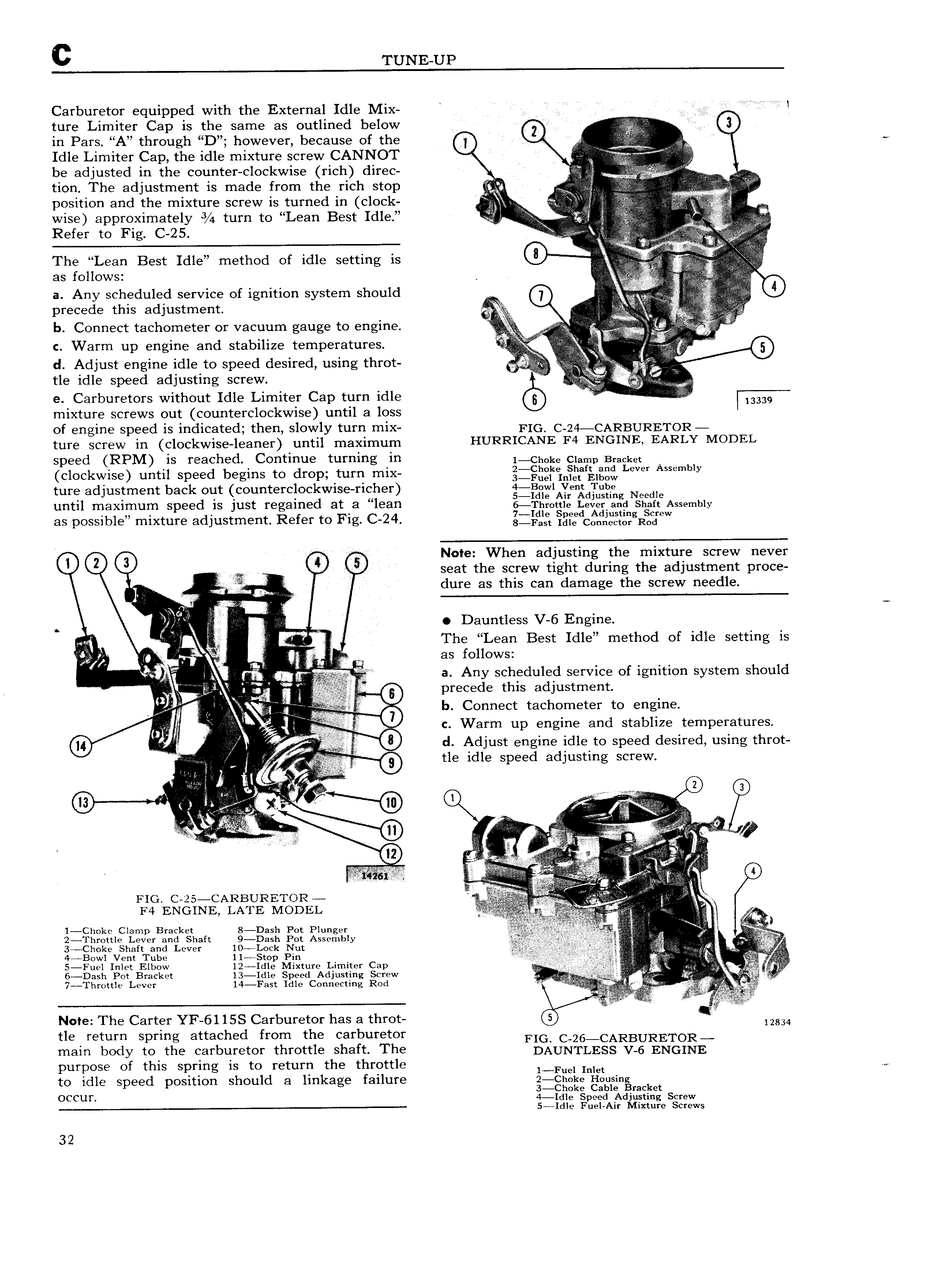
c TUNE UP Carburetor equipped with the External Idle Mix V A l tUI Limiter Cap is the same as outlined below 0 0 in Pars A through D however because of the 0 i V A Idle Limiter Cap the idle mixture screw CANNOT Q iv R be adjusted in the counter clockwise rich direc A VV M H tion The adjustment is made from the rich stop V V s s Q zav position and the mixture screw is turned in clock I E Wise eeereximeteiy s 4 tum te Lee Beet IdIe E EE Egigi itt Refer te Fig C 2 5 se ii i eE l E itE iE The Lean Best Idle method of idle setting is 0 a Any Senetinieti service of ignition system should r p 0 Eii Q 0 precede this adjustment iliiii E E b C X Mi Onnect tachometer Of V8Cuum gauge to eilglfle V it V W A ii i ii i C Wafm up engine and stabilize temperatures i 0 d Adjust engine idle to speed desired using throt v t 1 tle idle speed adjusting screw i 1 e Carburetors without Idle Limiter Cap turn idle ii i fum mixture screws out counterclockwise until a loss of engine speed is indicated then slowly turn mix EIGL C g4 CARBURETOR ture screw in clockwise leaner until maximum HURRICANE F4 ENGINE EARLY MODEL speed RPM is reached Continue turning in i ch0k clamp Bracket 4 clockwise until speed begins to drop turn mix l g in ff l g v Lsvss Assembly ture adjustment back out counterclockwise richer g 1AYfe d1L g Needl Y 1 S l 6 until maximum speed 1S just regained at a lean 6 Throttle Lexier a d siintt Assembly as pessibiei niixtnte adjustment Refer to Fig c 24 gji g5g Cg eR geW 0 0 Note When adjusting the mixture screw never 1 6 seat the screw tight during the adjustment proce 2 i V dure as this can damage the screw needle l Dauntless V 6 Engine L j I The Lean Best Idle method of idle setting is i as follows i M i L h we is i a Any scheduled service of ignition system s ould I 0 precede this adjustment H b Connect tachometer to el lgll l ix c Warm up engine and stablize temperatures Q I I if Vi 0 d Adjust engine idle to speed desired using throt i ii V 9 tle idle speed adjusting screw al i j 0 Q U e x w 0 i 0 s i i I 1 it i i J it t f iiV F ii FIG C 2 ii i T t CARBUR TOR t 4 F4 ENGINE LATE MODEL L gg it 2 I Choke Clamp Bracket 8 Dash Pot Plunger if Q F 2 Throttle Lever and Shaft 9 Dash Pot Assembly Q if J 3 Choke Shaft and Lever 10 rLock Nut ij j v Y v 4 Bowl Vent Tube 117Stop Pin i VTFC V T 5 Fuel Inlet Elbow 12 Idle Mixture Limiter Cap iw 6 Dash Pot Bracket 13 Idle Speed Adjusting Screw v j y w j A 7 Tin Ottie Lever 14 Fast Idle Connecting Rod A ii j iii e f X Note The Carter YF 61 15S Carburetor has a throt 6 Q 12834 tle return spring attached from the carburetor FIG C 26 CARBURETOR main body to the carburetor throttle shaft The DAUNTLESS V 6 ENGINE purpose of this spring is to return the throttle 1 Fu l Inlet to idle speed position should a linkage failure 2 ciit 1te 1 rtnising 3 Choke Cable Bracket Occult 4 Idle Speed Adjusting Screw 5 Idle Fuel Air Mixture Screws 32

 Next
Next