Ford Parts Wiki | GM Parts Wiki
Home | Search | Browse
Prev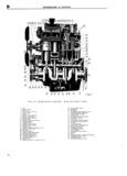
 Next
Next
300055
ee p UNIVERSAL SERl ES MANYQE1 JQ insulator mountin s attached to the frame side T T rail brackets The iear of the engrinedzransmission NOT E CEN ENGINEES EQUIPPEQD WITH EX assembly is supported by a iiublber insulator HAUS EMISSION CONTROL RQEMOVE THE mount ing under the rear of the transmission on AIR l UMP AH D STRIBU ION M NI the frame center cross member This cross member AN 1 LBACKFIRE DI ERIER is bolted to the frame side rails so that it can be SECT El F1 FCE ROCEDIEE dI O p d Wl lCIl I II 1OVlI1g tht tI 23l 1Sl IllS1SlOI1 OI CIlgl1 1C nq jiggggnngct hc Oi pressure and tgrnpgrgturg transmission assembly The rubber insulators allow sciidiiig unit Wiycs at the unitS fm ssc rmi Vsrsssl ssillsti is sifsstivsly p np ppppeep ppp ppppppp pipe pp ppp ppppppp neutralize engine vibration at the source manifold bv removing the stud m1ts The rubber insulator mountinggs shouldbe inspected 0 lZ iscon nect the spark plug cables at the plugs for separation and deterioration by jacking the and remove the cable bracket from the rocker arm power plant away from the frame near the sup cover stud ports Vlbfatlbfl 03 0t b iHl00tl V lZV absorb d by p jEllen nc ve the rocker arm cover by removing the separated or worn insulators They should be re attgmhiygig stud utS slsssd if fault q Attach a lifting bracket to the engine using existing head bolt locations Be sure the bolts 4 E Gr Strap i 25 E p 2 lpplli ipif ZF Eliiliplll E p l E t To be sure of an effective ground for the electrical OF Snihcic Lifting device ind take up au Slack i circuits a ground strap bridges the right front ig th t T t d It f h f t engine support to the chassis The connections of r LfCm Ovc C I YO fm sfmh IO S mm cacd 1 fm this strap must be kept clean appl i 1g1i r for proper ggmc l f f f C g gm f P operation of the electrical system Fmovc V the engine supports lower t c cjngmc slightly to permit access to the two top bolts on the flywheel housing D 5 IENGINE REMGVAL s lEllemove the bolts which attach the flywheel Should the engine require overhauling it is neces housing to the engine sary to remove it from thc vehicle The following t Pull the engine forward or roll the vehicle back P 00 dl l 0 00V0l 5 removal 0lf tho gl Oflly wards until the clutch cl ears the flywheel housing The engine transmission and transfer case may be Lift the gl fl 0f tlic V hiclo removed as a unit by removing in addition to the following procedure the radiator guard and the D 6 EZINIGINE DISASSLEMBLY 300055 Pl3t 5 lll tho BOOT P3f1 Engine disassembly is presented in the sequence a Drain the cooling system by opening the drain to be followed when the engine is to be completely cocks at the bottom of the radiator and lower right overhauled after removal from the vehicle Some side ofthe cylinder block of the operations of the procedure are also up b Disconnect the battery at the positive terminal Pll lb1 srpsratsly with tho gl 0 in the V0bi 1 i to avoid the possibiiity Of short cii Ciiiit proyided that wherever lnecessary the part of the c Remove the air cleaner horn from the carburetor cngmc lx bs Werksd on ls 51 st mad acC 1bl by and disconnect the breather hose at the oil Hller rcmovzli Of cflgmc accitssm 1 S OF sthsr pm ts l pipe Yll ll pilf 2p i 2 S i Ei Ei iZ ip 3Z l pd d Disconnect the carburetor choke and throttle in this pI OCcdm c that all Of the accessories have controls by l ss 1 s rhs clamp bolts and sst been removed prior to starting the disassembly S r wts and the oil has been drained Dlslcomlcct the fl l 1 t3llk tO fU l ZPUlmP bbc at In addition to the instructions covering operations lih ub PU mp by uriscr wi g the 0 lll 0tl g null for disassembling the engine out of the vehicle f Plug the fuel line to prevent fuel leakage special instructions are given to cover different g Remove the radiator ppp radiator grille support ol1i srsti yr s rs 1 iH vl s disssssmbly is doris with rods t e engine insta e p Rpppppp ppp upper ppp ippep ppp ippp ppppp by D rl s i sasssmblv i sre s s rhs si s sims loosening the hose clamps and slipping the clamps bs m um d m a svssbls engine mpaui taf1d Vvhcfc back on the hose If so equipped remove the heater pm C c a b modlfy sr dapt an cxlstmg Rpm hoses one to the water pump one to the rear of stand as necessary to accommodate the engine If the cylinder head in the same manner as l g f p Siimd is tot d take Calc t R A the four bolts from the fan hub and fc perform disassembly operations in al manner that I cmove will protect personnel against an accident and t he mrs rhs f hub sm fas mdss ppgppp ppp pp parts pppippp damage j Remove the four radiator attaching screws Re y5 q g movc the radiator and shmiid as mc unit NOTE li the engine is being disassembled because k Remove the starting motor cables Remove the of possible valve failure check the valve tappet starting motor clearance before disassembly Improper valve I Dis enn ec the wires rrprn the alternator or l a 1 1 bs thc p SS b1 a s Of failure indicating a need for more frequent valve gene ator tD1sconr ect the ignition primary wire checks and adjustments at t e igm ion coi j 41