Ford Parts Wiki | GM Parts Wiki
Home | Search | Browse
Prev
 Next
Next
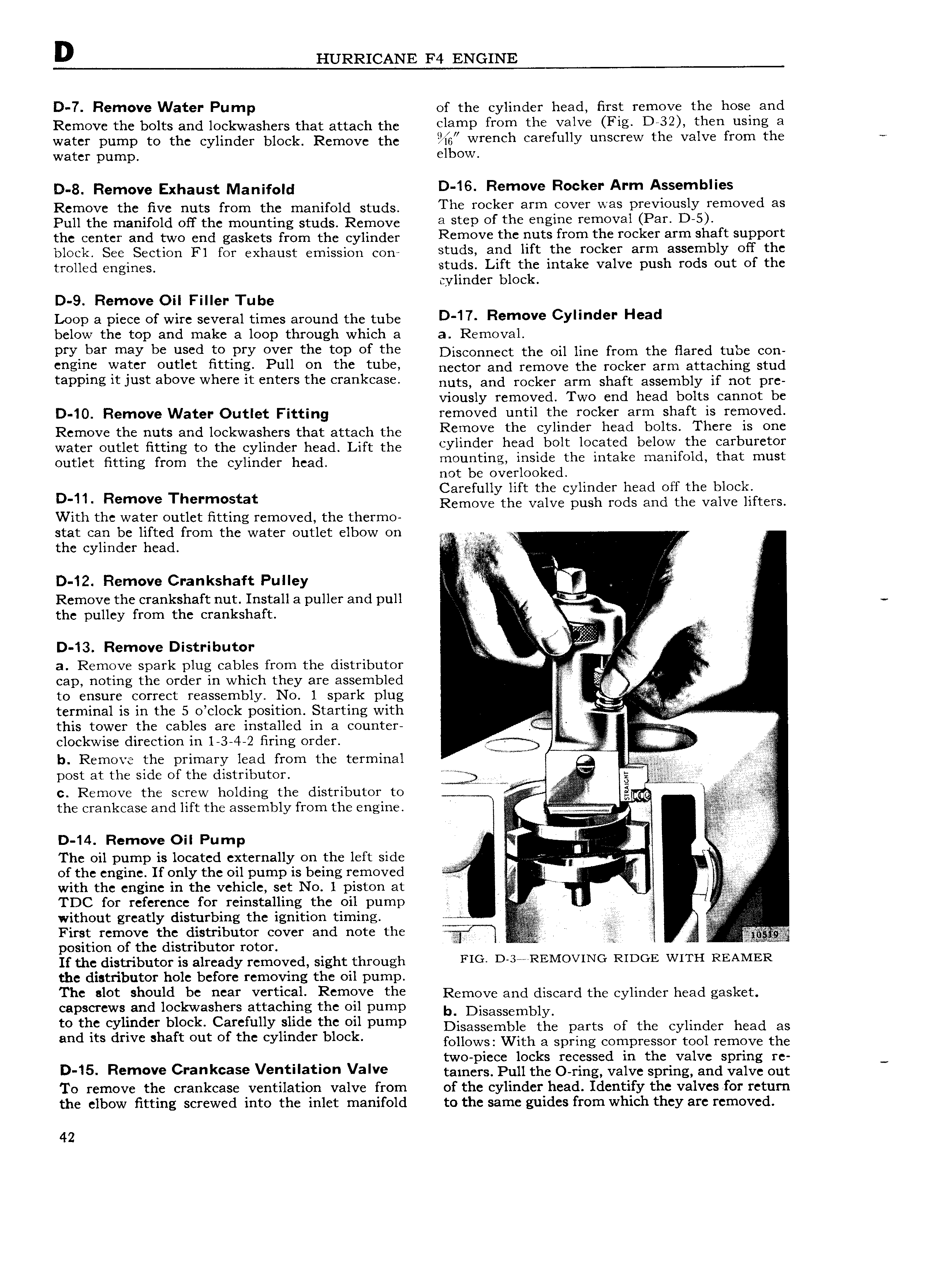
D HURRICANE F4 ENGINE D 7 Remove Water Pump of the cylinder head first remove the hose and Remove the bolts and lockwashers that attach the clamp mm the valve FIg D 32 then usmg 3 water pump to the cylinder b Oek Remove the wrench carefully unscrew the valve from the water pump 6 GW D 3 Rempye Exhaust N anif d D 16 Remove Rocker Arm Assemblies Remove the five nuts from the manifold studs The Yoeker arm eOVeI Wes PIeVIouslY removed as Pull the manifold off the mounting studs Remove 3 Step Ot the engine IemoV3I P8 D 5 the center and two end gaskets from the cylinder R f 0V th puts fmm the meker mm shatt SIIPPOI t block See Section Fl for exhaust emission con tUd and htt the rocket atm assembly ott the trgugd engmee studs Lift the intake valve push rods out of the cylinder block D 9 Remove Oil Filler Tube Loop a piece of wire several times around the tube D 1 7 F m v CYllnde Head below the top and make a loop through which a a Removal PI Y bat maY be used to PIY OVeI the tOP Ot the Disconnect the oil line from the fiared tube con eogme Watet outlet ottm Pull on the tubs nector and remove the rocker arm attaching stud tapping it just above where it enters the crankcase nuts aud mekey m m Shaft assembly if not pre viously removed Two end head bolts cannot be D 10 Remove Water Outlet Fitting removed until the rocker arm shaft is removed Remove the nuts and lockwashers that attach the R v the oylmoet head bolts There ls ooo water outlet fitting to the cylinder head Lift the eYlmoet he oo bolt loooteo oelovt the Carburetor Outlet Btting from the eyuudc head mounting inside the intake manifold that must not be overlooked Carefully lift the cylinder head off the block Di11 R m V Th rm Stat Remove the valve push rods and the valve lifters With the water outlet fitting removed the thermo stat can be lifted from the water outlet elbow on u the cylinder head g Z A D 12 Remove Crankshaft Pulley i j gf Remove the crankshaft nut Install a puller and pull n I V I the pulley from the crankshaft l e r I Q D 13 Remove Distributor R V I a Remove spark plug cables from the distributor E H cap noting the order in which they are assembled ij to ensure correct reassembly No 1 spark plug 1 I V li V e terminal is in the 5 o clock position Starting with a r this tower the cables are installed in a counter V A E clockwise direction in 1 3 4 2 firing order y r r V b Remove the primary lead from the terminal om g post at the Sid of fh diStfIl 0Y r 3 W w p up G c Remove the screw holding the distributor to s g i j mw the crankcase and lift the assembly from the engine I e D 14 Remove Oil Pump T ae The oil pump is located externally on the left side l i r of the engine If only the oil pump is being removed e r V if with the engine in the vehicle set No 1 piston at z to L i TDC for reference for reinstalling the oil pump i without greatly disturbing the ignition timing V j First remove the distributor cover and note the ii position of the distributor rotor if O ii i R If the distributor is already removed sight through FIG D 3e REIVIOVING RIDGE WITH REAIVIER the distributor hole before removing the oil pump The slot should be near vertical Remove the Remove and discard the eylmdey heed gasket capscrews and lockwashers attaching the oil pump b Disassembly t0 yI d f block emfuuy shdc h pump oisassembic the parts Or the cylinder head as and its dnvc h ft out of th vh d f block follows With a spring compressor tool remove the two piece locks recessed in the valve spring re D 15 Fl m v Crankcase V f lat Valve ramers 1 u11the ormg vaive spring and vaive our To remove the crankcase ventilation valve from of the cylinder head Identify the valves for retum the elbow fitting screwed into the inlet manifold to the same guides from which they are removed 42