Ford Parts Wiki | GM Parts Wiki
Home | Search | Browse
Prev
 Next
Next
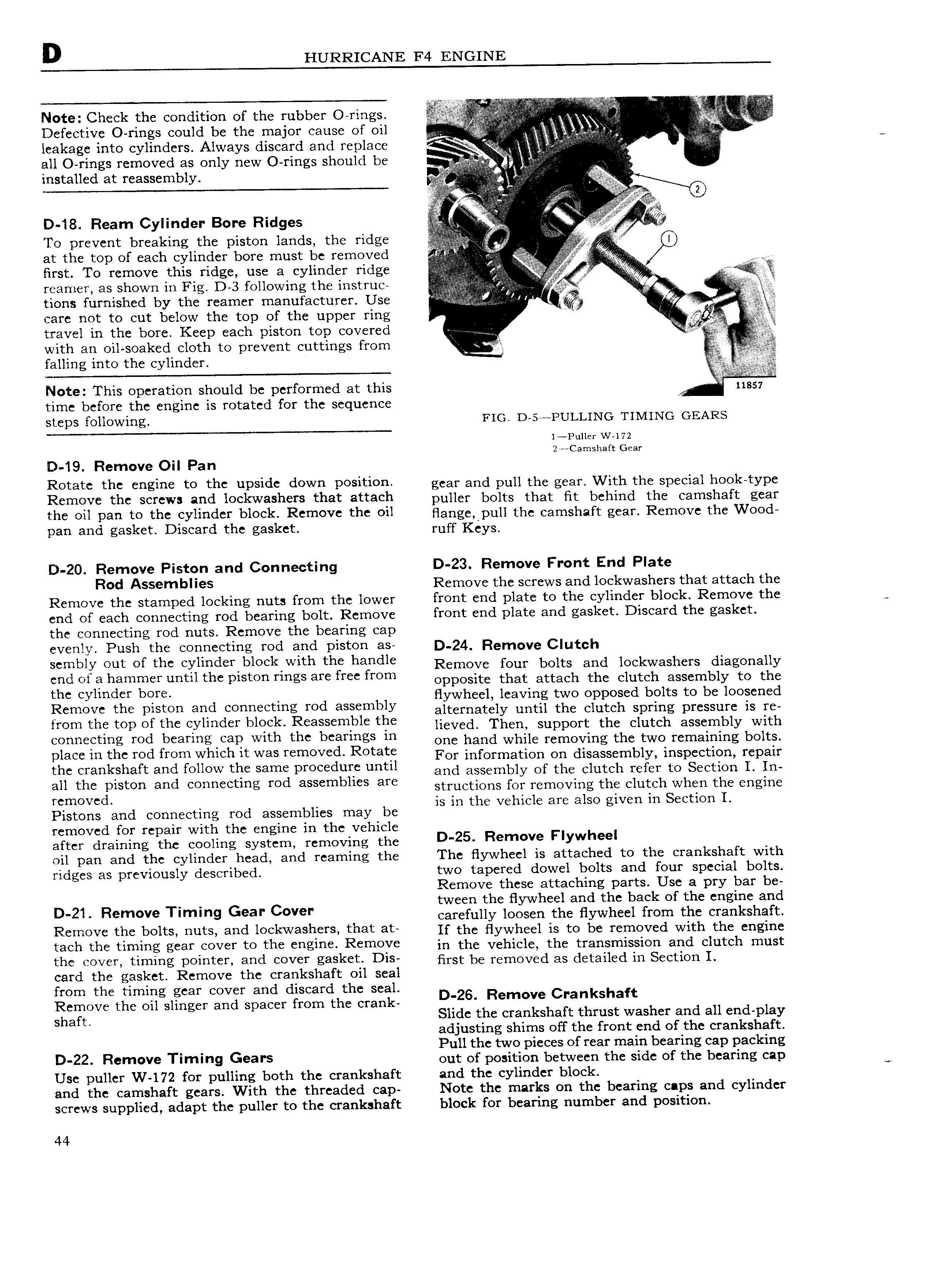
D HURRICANE F4 ENGINE V f f 3 i f Note Check tht COI lCllflOl 1 of the rubber O fi gS Defective O rings could be the major cause of oil V VAV V A leakage into cylinders Always discard and replace v i i I all O rings removed as only new O rings should be V Z V g installed at reassembly i i V VV l l w e l l l ll 0 v l iiV Q 2 V ii D 18 Ream Cylinder Bore Ridges v l Q To prevent breaking the piston lands the ridge at the top of each cylinder bore must be removed H V if VV V V first To remove this ridge use a cylinder ridge me r rearner as shown in Fig D 3 following the instruc l V eg tions furnished by the reamer manufacturer Use ii t care not to cut below the top of the upper ring I t travel in the bore Keep each piston top covered liii M with an oil soaked cloth to prevent cuttings from falling into the cylinder s l Note This operation should be performed at this i 11857 time before the engine is rotated for the sequence steps following FIG D 5 PULLING TIMING GEARS l Puller W 172 2r Camshaft Gear D 19 Remove Oil Pan Rotate tht gl to tht PSld down P0Sltl0 gear and pull the gear With the special hook type Remove the screws and lockwashers that attach pulley bolts that ht bchind the eamshaft gear tht pail to thC cylinder block Remove thC oil flange pull the camshaft gcagg Rgmgvc thc Wggd pan and gasket Discard the gasket ruff Keys D 20 Remove Piston and Connecting D 23 Remove Front End Plate R d A mbll Remove the screws and lockwashers that attach the Remove the stamped locking nuts from the lower front end plate to the cylinder block Remove the end of each connecting rod bearing bolt Remove front end plate and gasket Discard the gasket the connecting rod nuts Remove the bearing cap evenly Push the connecting rod and piston as D 24 Remove C uteh sembly out of the cylinderlblocklwith the handle Remove l Om bolts and lmskwashcrs diagonally end of a hammer until the piston rings are free from Opposite that attach the clutch assembly to the thc cylinder bore flywheel leaving two opposed bolts to be loosened Remove the plseen sed eemleetmg md assembly alternately until the clutch spring pressure is re lrom the top of the cylinder block Reassemble the llsvscl Then support the Clutch assembly with connecting rod bearing tap With th btamlgs m one hand while removing the two remaining bolts plaee m the md rem Whleh lt was removed Rotate For information on disassembly inspection repair the crankshaft and follow the same procedure until and assembly Of the Clutch Ysfsr to Section L ln an the plsten and eenneetmg wd assemblies are structions for removing the clutch when the engine Yemm Cd is in the vehicle are also given in Section I Pistons and connecting rod assemblies may be removed for repair with the engine in the vehicle after draining the cooling system removing the D 25 Remove F lYWh l oil pan and the cylinder head and reaming the The flywheel is attached to the crankshaft with ridges as previously described two tapered dowel bolts and four special bolts Remove these attaching parts Use a pry bar be tween the flywheel and the back of the engine and D 21 Rem ve T m g Gear C ver carefully loosen the flywheel from the crankshaft Remove the bolts nuts and lockwashers that at If the nywheel is to be removed with the engine tach th timing gw 0V F to the gl R m0V in the vehicle the transmission and clutch must the cover timing pointer and cover gasket Dis nm be removed as detailed in Section 1 card the gasket Remove the crankshaft oil seal from the timing gear cover and discard the seal Remove the oil slinger and spacer from the crank DT26 Remove Crankshaft shaft Slide the crankshaft thrust washer and all end play adjusting shims off the front end of the crankshaft Pull the two pieces of rear main bearing cap packing 0 22 R m V Tlmln9 Gears out of position between the side of the bearing cap we Use puller W 172 for pulling both the crankshaft and the cylinder block and the camshaft gears With the threaded cap Note the marks on the bearing caps and cylinder screws supplied adapt the puller to the crankshaft block for bearing number and position 44