Ford Parts Wiki | GM Parts Wiki
Home | Search | Browse
Prev

 Next
Next
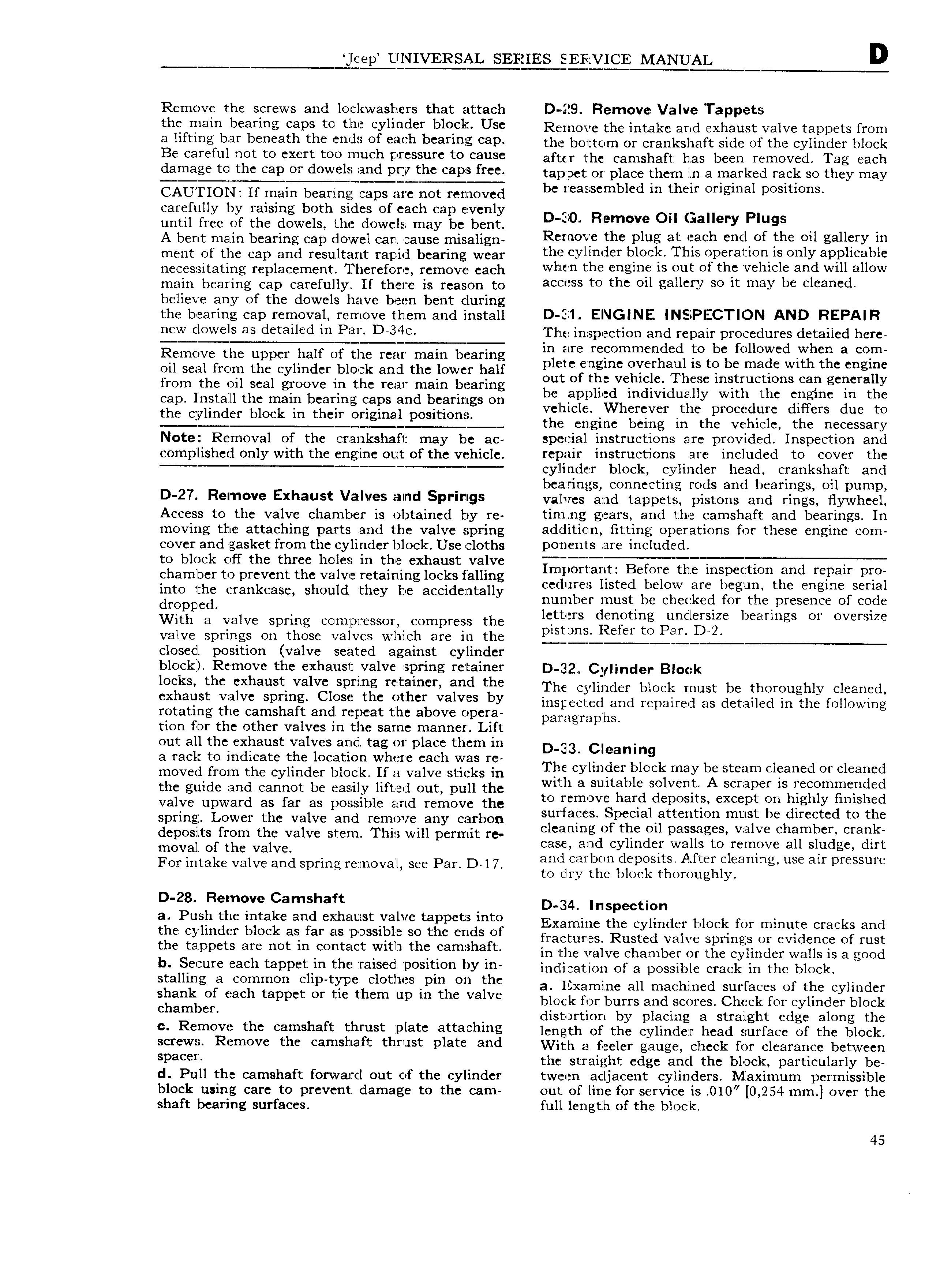
leep UNIVERSAL SERIES SERVICE MANUAL D Remove the screws and lockvwashers that attach D 29 Remove Valve Tappets thc main bearing caps ts ih cyflilndsr blsck Use Reinpw the intake spd exhaust valve tappets ri Om a 1ifti s bar bs th rhs is sf h bearing cap the bottom or erapipsiiart side ofthe cylinder block Be C3I l l1l not to C X I t tOO HNJCI 1 p I CS Eil1I C to CSHSC Elfjjfiy the Camshaft has bcgn f jm Vcd gg gach damage ts tha Cap Ot dswsls and PTY ths caP 5 fY tzapjpet or place them in a marked rack so they may CAU I ION If main bearing caps are not removed be l S mb1 d m then OI lgmal pOSmOnS carefully by raising both sides of each cap evenly until free of the dowels the dowels may be bent D l 0 R m v Oll iauery Plugs A bent main bearing cap dowel can cause misalign R Cmollic ths Plug at laach d sf the 0 1 gallery m ment or the cap and resuiemt rapid ipeanng wear th yl1 isr blsrk 1 his r sratr 1s ly i ph bl necessitating replacement Therefore remove each Vvtlrtm the cngmt IS wt sf th Vslmls and will allow main bCar ing Cap Carc u y If tjhmyc is reason to access to the oil gallery so it may be cleaned believe any 0f the dowels have been bent during the bearing cap removal remove them and install D El1 ENGINE INSBPIECTION AND REPAIIR W l0W lS a detailed in Pali D 34 The inspection and repair procedures detailed here Remove the upper hair pr ppp main bearing 1q s mm g t b f gsd gc oil seal from the cylinder block aznrl the lower half p we cnglnc Over gu ls H C m l W1 t C cngmc from thc Oil sca mov in the In 4 main be rin out of the vehicle These instructions can generally g C mi a g le a l1 d 1nd1v1duall with the engine in the cap Install the main bearing caps and bearings on L pf y d H d the cylinder block in their original positions vc uCl WhcrqV r thc proudllrc I Us uc to M M the engme being in the vehicle the necessary Note Removal of the crankshaft may be ac special instructions are provided Inspection and cornpilished only with the engine n lt of the vehicle repair instructions are included to cover the T cylinder block cylinder head crankshaft and bearings connecting rods and bearings oil pump D 27 Remove Exhaust Valves aincl Springs valves arid rappers pistons and rings flywheel Access to the valve chamber is obtained by re timing gears and the camshaft and bearings In moving the attaching parts and the valve spring addition fitting operations for these engine com cover and gasket from the cylinder block Use cloths DOZHCHTS arc included to block off the three holes in the exhaust valve i j f T 1 E M iMT chamber to prevent the valve retaining locks falling vnrlpor Quit c mic I ic Lnipcc Km lan rcpau pioi into the cmnkcasg Should they be accidentally cedures listed be ow are egun tie engine seria dropped nurnber must be checked for thelpresence ol code with 3 valve Spring COmW SSC r Compress the letters denoting unclersize bearings or oversize valve springs on those valves which are in the closed position valve seated against cylinder block Remove the exhaust valve spring retainer 3 2 C y indei Bleek locks the exhaust valve spring retainer and ths The wliiidey bloc imist be thoroughly cleaned sxhavst vars srms 1 s thc 5 h r valves by ipsppapp app repaired as detailed ip nip rpiipwipp rotating the camshaft and repeat the above opera pm ZlgmphS tion for the other valves in the same manner Lift out all the exhaust valves andl tag or place them in D 3r3 clieaning a racl to indicate the location where each was re moved from the cylinder block If a valve sticks in The Cylmlicr bl k may be Steam Clltancd Or cllsancd the guide and cannot be easily lifted out pull the wml avsmtable s lV F A Semper ls T mm d d valve upward as far as possible and remove the to f m V hatd d pl s1t sxc pt On highly Hrllshcd Spring Lower the Valve and Tcmove any Carbon surfaces Speciallattention must be directed to the deposits from the valve stem This will permit re clmnmg Of the ml r ssas s vlahfie Chambcn Cralqk case and cylinder walls to remove all sludge dirt moval of the valve y Af I x For intake valve and spring removal see Par D l 7 jfjr FEE I S1 r L L y 3nmg USC an pmssure D 28 Remove Camshaft D 34u Inspection a Push tlitc mtakcranfd cithglust Xalvc tappcts mt Examine the cylinder block for minute cracks and gs iylmd f block ls at lsjcrp2SS1li2ic thc siggs fi fractures Rusted valve springs or evidence of rust C zppc S are no m Fon dc Wl 1 K Fam S in the valve chamber or the cylinder walls is a good b Secure Each taPP t m tht V a1 d Ypalsltlon by m indication of a possible crack in the block Staumg 3 Common Chp tYp c Clothcs rpm OH thc a Exazmine all machined surfaces of the cylinder shank Of sash tappct Or me them up lm the Valve block for burrs and scores Check for cylinder block Chambcn distortion by placing a straight edge along the C R mOV th Camshaft thrust Plate attaching length of the cylinder head surface of the block Screws R m0V the sh ft tmust Plate and W ith a Beeler gauge check for clearance between Space the straight edge and the block particularly be d Pull the camshaft forward out of the cylinder tween adjacent cylinders Maximum permissible block using care to prevent damage to the cam out of l ine for service is 010 0 254 mm over the shaft bearing surfaces full length of the block 45

 Next
Next