Ford Parts Wiki | GM Parts Wiki
Home | Search | Browse | Marketplace | Messages | FAQ | Guest
Prev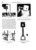
 Next
Next
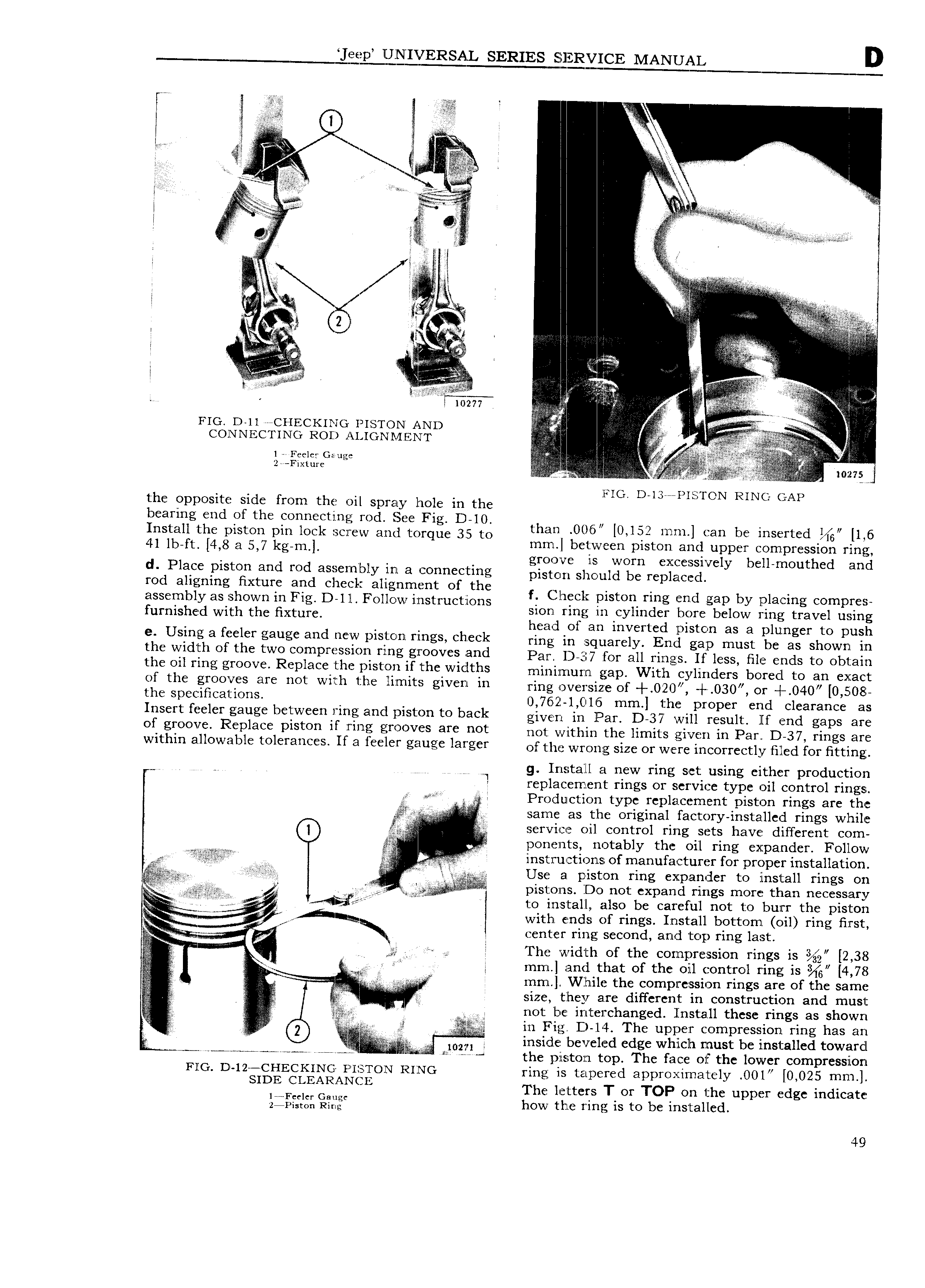
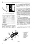
Jeep IEQQEVERSAL SERIES EEQEERYICE MANUAL D l l A S I L xs ji V s I V s F I e l l 5 I l 4 I s j 4 F l i i I ggi t E l i I I E S ll In E EEEEEEEE E EE EE E EiE E s s EE ESSE S S S I E Ii ii EEV I ll E zviazv s I l VA i J II I I I I l l V E A A AE i is i 5 l l V 1 V a ff V l S if V A E E I E I l I I FIG on SSSS CHECKING rST f NI AND 2 I l S V i PF1 s CONNECTING ROD ALIGl l l IE l J 1 I A V s s ii V sr 9 i I F 1 Gauge l A 2I F lv 0 7 FIG D 13aaI IsToN RING GAP the opposite side from the oil spray hole in the bearing end of the connecting rod See Fig D 10 1 Install the piston pin lock screw and torque 35 to tlmml ll 6 lO l 2t mm an be Inserted lh 41 lm he E W kgeml Qiilgvs 3sF s Z lf l b H E Ei IEE I s I d Place piston and rod assembly in a connecting pistcm Shguld be rs p aC d rod aligning fixture and check alignment of the f Cl I t P d b 1 A assembly ss shown in rig nn Follow ms c s r E E i Qs 510 Y s Z e 1 L fumished Wim the Hme Z l 2 s lilssssi pistin pliingervfo phsg e Usinsa fceier gauge and new PiS t O hlY lhgS check ring in squarely End gap must be as shown in th width Of th tW0 0mPF S10h Yl g giF 00V Bhd Par 1 37 for all rings If less tile ends to obtain th Oil Tihg gY00V R Dl3 th Pisthh rf the Widths minilnurrl gap With cylinders bored to an exact of the grooves are not with the limits given in ring V i2 e Of 0Q O3 Or 4 0 5 thi SD F1hC3li10hS 0 76 2 l O l 5 mm the proper end clearance as IHSCIT f B lCI g3ug b tW H 1 1flg3I 1Cl 1St I l to back givgn in PaI evil I Su1t End gaps are of gf00V R Dl3 Piston if V m i OOV S 9Y h0t not within the limits given in Par DI 37 rings are Within 6 ll0W3bl tOl Y3h If 3 l l V g iugc l3Y g Y of the wrong size or were incorrectly filed for fitting W V 1 g Insatalll a new ring set using either production I replacernent rings or service type oil control rings e A Production type replacement piston rings are the s s I E s l o i same as the original factory installed rings while E V service oil control ring sets have different com 5 V poneznts notably the oil ring expander Follow ss l 5 instriictionsc of manufacturer for proper installation if 22 Use a piston ring expander to install rings on Vs7 Es g s I ist02 S D0 not expand rings more than necessary i I j I to install also be careful not to burr the piston one I l f hg with ends of rings Install bottom oil ring first X l center ring second and top ring last I I s I I The width of the compression rings is 2 38 T E s Q s J mm and that of the oil control ring is 4 78 s iX I z l mm While the cornpression rings are of the same K lliiiiiilllii ii Eii in size they are different in construction and must il F ii I s not be interchanged Install these rings as shown l I 2 x i in Fig D Zl4 The upper compression ring has an r i i sr if iiii l l inside beveled edge which must be installed toward I2 10 A I II I the ls ton top The face ol the lower compression FIG D 12 CHECKING I IsTo1N RING ring is tapered apprexirnately O0l 0 025 mm SIDE l LEARAN I The letters T or TOP on the upper edge indicate i f l 1 iill how the ring is to be installed 49