Ford Parts Wiki | GM Parts Wiki
Home | Search | Browse | Marketplace | Messages | FAQ | Guest
Prev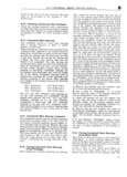
 Next
Next
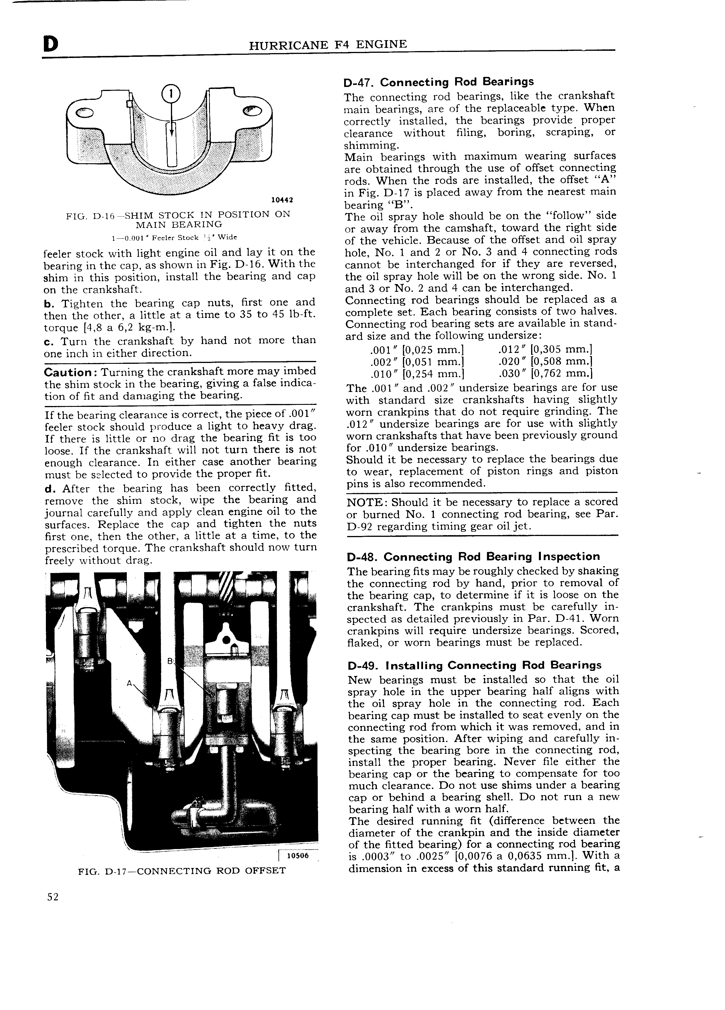
D 47 Connecting Rod Bearings The connecting rod bearings like the crankshaft Q main bearings are of the replaceable type When correctly installed the bearings provide proper clearance without filing boring scraping or shimining Mein bearings with maximum wearing surfaces e r I are obtained through the use of offset connecting rods When the rods are installed the offset A n il E i i i in Fig D 17 is placed away from the nearest main bearing B rrr Dsmi sHrM STOCK IN POSITION ON The oil spray hole should be on the follow side 140 0l l A N1 Bifcerlsrivkd O agvay go tllge can1sh fi 1tOWHaI d thedrigfit Side s 2 1 o t e ve ic e ecause o e 0 set an oi spray f lCI stock with light I 1glIl oil and lay lt OD tl l hglg NO 1 and 2 Or No 3 and 4 cgnnggting rgds bfififlng ifi tht CBD 85 shown lll Fig D l6 With the cannot be interchanged for if they are reversed shirn in this position install the bearing and can the oil spray hole will be on the wrong side No 1 on the crankshaft and 3 or N0 2 and 4 can be interchanged b Tighten the bearing cap nuts first one and Connecting rod bearings should be replaced as a then the other a little at a time to 35 to 45 lb ft complete set Each bearing consists of two halves torque 4 8 a 6 2 kg m Connecting rod bearing sets are available in stand c Turn the crankshaft by hand not more than ard srze and the rouowmg nndersrzer one inch in either direction 001 0 025 mm 012 0 305 mm 002 0 051 mm 020 0 508 mm gP r g hi PkSh rt m r f Y F d 010 0 254 mm 0s0 0 762 mm gfnsoggtsgzcd ggmzinzaialggggiigg a 8 sc m me Thi 001 Smdi 002 unde i efbeaii1ngs are forhuise wit stan ar size cran s a ts aving sig ty If the bearing clearance is correct the piece of 001 worn crankpins that do not require grinding The feeler stock should produce a light to heavy drag 012 undersize bearings are for use with slightly If there is little or no drag the bearing fit is too worn crankshafts that have been previously ground loose If the crankshaft will not turn there is not for O10 undersize bearings enough clearance In either case another bearing Should it be necessary to replace the bearings due must be Seleeted to provide the proper it to wear replacement of piston rings and piston d After the bearing has been correctly fitted Pms rs also reeommerrdeo 1 remove tho shim srooki Wins the bearing and NOTE Should it be necessary to replace a scored journal Carefully and apply Clean engine og to the or burned No 1 connecting rod bearing see Par surfaces Replace the cap and tig ten t e nuts first one then the other a little at a time to the prescribed torque The crankshaft should now turn freely without drag D 48 Connecting Rod Bearing Inspection L Q V i The bearing fits may be roughly checked by shaking i U ii n i V the connecting rod by hand prior to removal of i the bearing cap to determine if it is loose on the i crankshaft The crankpins must be carefully in j f spected as detailed previously in Par D 41 Worn f i crankpins will require undersize bearings Scored flaked or worn bearings must be replaced M Bi D 49 Installing Connecting Rod Bearings T3 New bearings must be installed so that the oil fl spray hole in the upper bearing half aligns with 1 i ii the oil spray hole in the connecting rod Each i f ff bearing cap must be installed to seat evenly on the I connecting rod from which it was removed and in rrr f t I i the same position After wiping and carefully in j NQ glu Sp Cti1 lg the bearing bore in the connecting rod l i V ii rs install the proper bearing Never file either the lr Q bearing cap or the bearing to compensate for too I much clearance Do not use shims under a bearing Ki cap or behind a bearing shell Do not run a new i bearing half with a worn half Z r i e The desired running fit difference between the I i diameter of the crankpin and the inside diameter J r r i j of the fitted bearing for a connecting rod bearing l is O003 to 0025 0 0076 a 0 0635 mm With a FIG D 17 CONNECTING ROD OFFSET dimension in excess of this standard running fit a 52