Ford Parts Wiki | GM Parts Wiki
Home | Search | Browse
Prev
 Next
Next
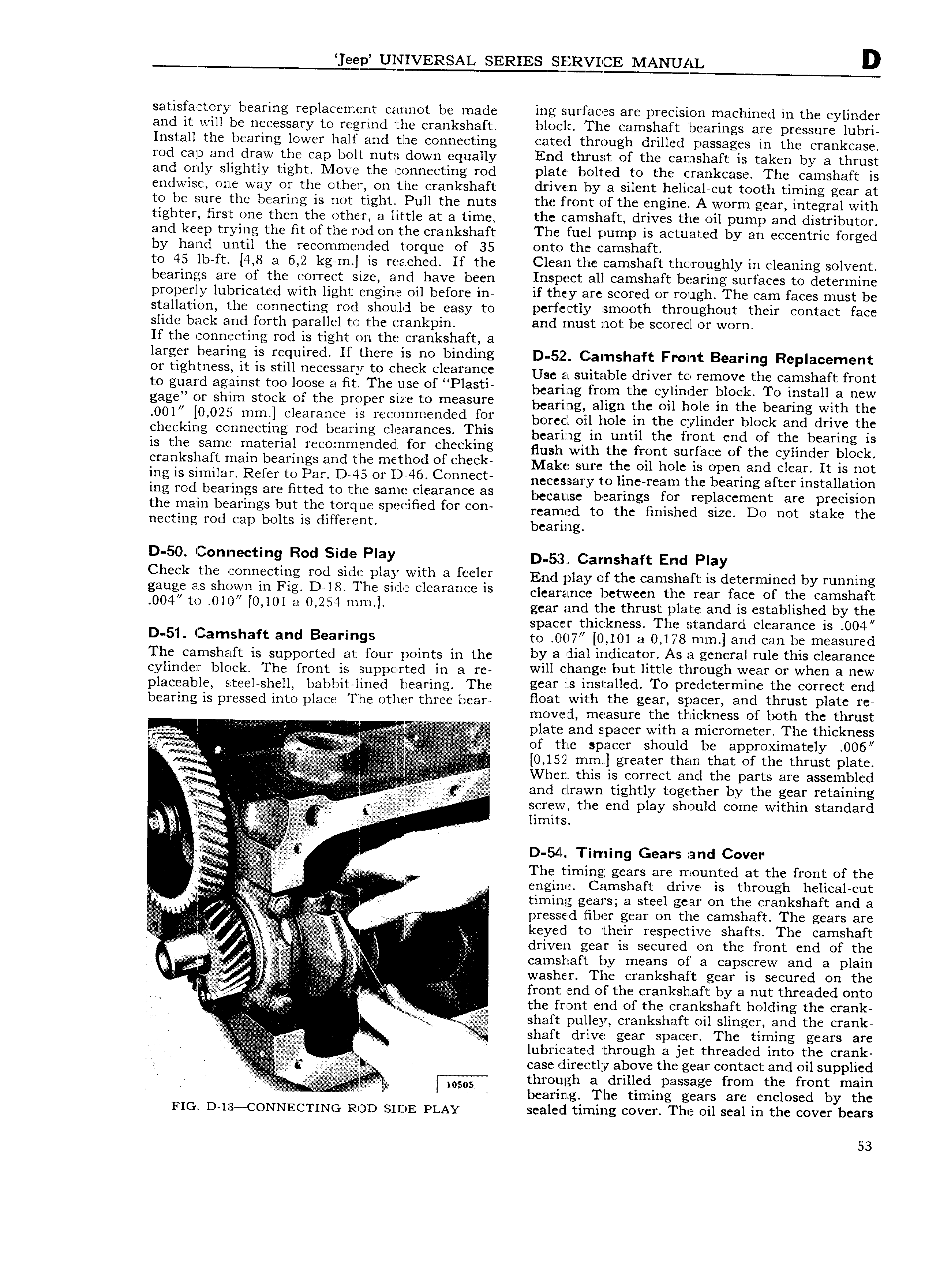
eep UNIVERSAL SERIES SHZR C CE MANUAL D satisfactory bearing replacement cannot be made ing surfaces are precision machined in the cylinder and it will be necessary to regrincl the crankshaft blocl The camshaft bearings are pressure lubri Install the bearing lower half and the connecting cated through drilled passages in the crankcase rod cap and draw the cap bolt nuts down equally Encl thrust of the camshaft is taken by a thrust and only slightly tight Move the connecting rod plate bolted to the crankcase Th e camshaft is endwise one way or the other on the crankshaft driven by a silent helical cut tooth timing gear at to be sure the bearing is not tight Pull the nuts the front of the engine A worm gear integral with tighter first one then the other a little at a time the camshaft drives the oil pump and distributor and keep trying the fit of the rod on the crankshaft The fuel pump is actuated by an eccentric forged by hand until the recommended torque of 35 onto the camshaft to 45 lb ft 4 8 a 6 2 kg m is reached If the Clean the camshaft thoroughly in cleaning solvent bearings are of the correct size and have been Inspect all camshaft bearing surfaces to determine properly lubricated with light engine oil before in if they are scored or rough The c am faces must be stallation the connecting rod should be easy to perfectly smooth throughout their contact face slide back and forth parallel to the crankpin and must not be scored or worn If the connecting rod is tight on the crankshaft a larger bearing is required ll there is no binding D 5 2 Camshaft Front Bearing Replacement er tightness it is still C s sa Y te Check clearance Use a suitable driver to remove the camshaft front 0 sears against tee here el fit The repel PleS seeing rr Om the ey ii ia neck re insaii a new sage Of shim Steck ef the p rY F smc rs mcasum bearing align the oil hole in the bearing with the 001 l0 020 mr l clearance rs re mme ded fer bored oil hole in the cylinder neck and drive the checking connecting rod bearing clearances This bcsmsg in until thc rcnt cnd Of thc bcacing is is the same material recornrnendecl for checking Hush with thc mnt sucfccc cf thc cyundcc block crankshaft mam bearings and the m thO0 ef Check Make sure the oil hole is open and clear It is not lng ls sl mllals Refer te Per DAS OY D 4 s Cenneet necessary to line rearn the bearing after installation ing rod bearings are fitted to the same clearance as bccausc bcacings fm rcplaccmcnt acc prccisicm the mam bearings but the terque slmclslsd fer CO reamed to the finished size Do not stake the necting rod cap bolts is different bcacmg D 50 Connecting Rod Side Play D 5 g C 4arnshaft End pray Check the connecting rod side play with n fecler End play ofthe cainslreft is determined by running gauge es ShOW in Fl D l8 The sid l 3Ya is clearance between the rear face of the camshaft 004 U 010 l0 l0l 3 0254 ml l gear and the thrust plate and is established by the spacer thickness The standard clearance is 004 D 51 Camshaft and Bearings to l l7 0 101 a 0 178 mm and can be measured The camshaft is supported at four points in the by H dial lI1diC3tQI As 21 general rule this clearance cylinder block The front is supported in a re will h lTl ECC but ll tl hl 0l lgh VY 6l1 OT Wh 8 W placeable steel Snell babbit lined bearing The gear is installed To predctermine the correct end bearing is pressed into place The other three bear fleet Wlth h g 3l D3 i and thfusli plate 1 5 moved measure the thickness of both the thrust Y if A p plate and spacer with a micrometer The thickness Z i 2 r r Q i ti l jg of the spacer should be approximately ClO6l is i ii 0 152 mm greater than that of the thrust plate 0 ifi i l ii zii When this is correct and the parts are assembled f i g a il T Z and clrawn tightly together by the gear retaining as S 1 el the Gnd play should come within standard Kjcvc I limits fii lQ i D 54 l Tlllhihg Gears and Cover ei 4 The timing gears are mounted at the front of the 4 i engine Camshaft drive is through helical cut Y i j V ll c timing gears a steel gear on the crankshaft and a l is pressed fiber gear on the camshaft The gears are is keyed to their respective shafts The camshaft e i ll iiii lg l driven gear is secured on the front end of the i cfg f E V V camshaft by means of a capscrew and a plain r D i i washer The crankshaft gear is secured on the A si l iii r is ii front end of the crankshaft by a nut threaded o nto if V i 1 A the front end of the crankshaft holding the crank V piss shaft pulley crankshaft oil slinger and the crank i i i f Yi Q Ms s i shaft drive gear spacer The timing gears are i I i T lubricated through a jet threaded into the cranli e c case directly above the gear contact and oil supplied csal l Q I 1 i if I Yf r Eas EE s QT E l i S Ey Z Flo D 18 CONNECTING Roo sion PLAY sealed timing cover The oil seal in the cover bears 53