Ford Parts Wiki | GM Parts Wiki
Home | Search | Browse
Prev
 Next
Next
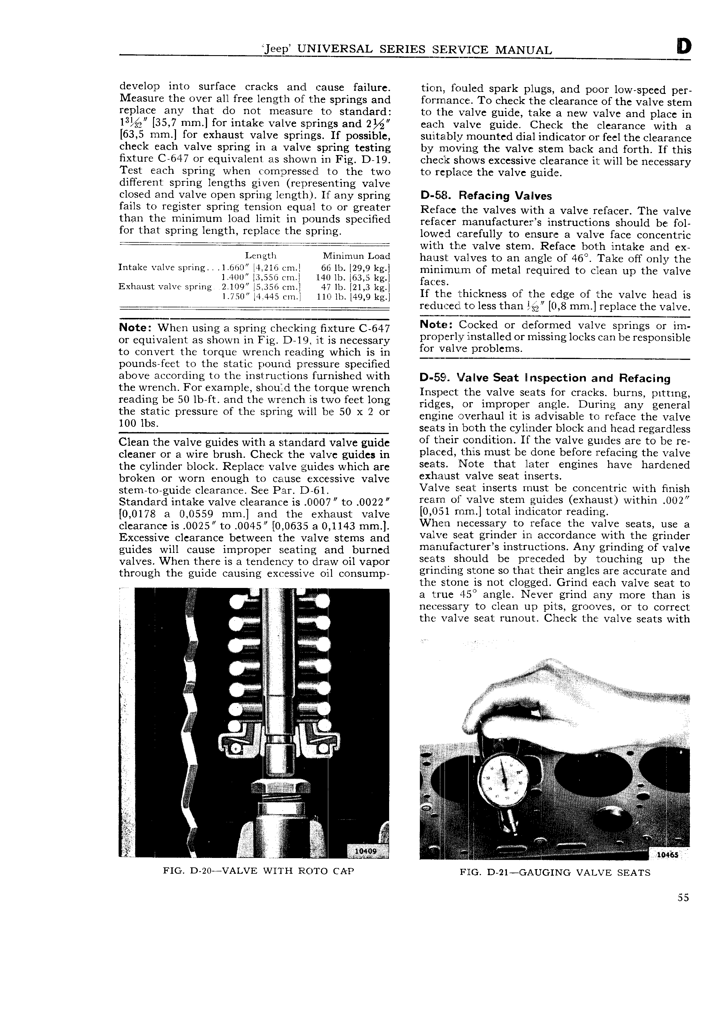
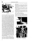
ep QIERSAL SERIES SERVICE MANUAL D develop into surface cracks and cause failure tion fouled spark plugs and poor low speed per Measure the over all free lengtlh of the springs and forrnance To check the clearance of the valve stem replace any that do not measure to standard to 1 he valve guide take a new valve and place in l3 2 35 7 mm for intake valve springs and 2 each valve guide Check the clearance with a 63 5 mm for exhaust valve springs If possible suitably mounted dial indicator or feel the clearance check each valve spring in a valve spring testing by zmovfing the valve stem back and forth If this fixture C 647 or equivalent as shown in Fig D 19 check shows excessive clearance it will be necessary Test each sprin when cornpressedl to the two to replace the valve guide g d1H I IIt spring lengths g1Sven representing valve closed and valve open spring length If any spring D Eiiiil Fiefacing Valves f81lS Q Wg t F Spfmg t Q iQ tqllal U OT gY t Y Reface the valves with a valve refacer The valve than tht mtmmum 10Hd hmlt m 190l1 1d D 1H d refacer manufacturer s instructions should be fol for that spring length replace the spring lower earefully to ensure a valve face concentric ii with the valve stem Reface both intake and ex Length Ntinimun Load hanst valves to an angle of 46 Take off only the Intake valve spring 1 660 4 216 crm 661b IQ9 9 kg l minirnurn of metal required to clean up the valve l 400 3 556 em 1140 1b 63 5 kg faces Exhaust valve spring 2 lO9 5 356 cm 47 lb 21 3 kg H tih thickness Of Th edge Of the Valve head is l 7T0 4 445 yn 110 1b 49 9 kg L yj i 1 Q reclucecl to less than E g2 0 8 mm replace the valve Note When using at snnnn enenrnng nnenn can N l 1F k gf i Vive S1 gS Or ig or equivalent as shown in Fig 1D 19 it is necessary ll i V St S Of SS g OC S Can SS O S S to convert the torque wrench reading which is in f 2E j rO mS pounds feet to the static pound p ressure specified above according to the instructions furnished with D 55 Valve Seat inspection and Refacing the WY Ch FOY X3mP1 Should th t O fl Wrench Inspect the valve seats for cracks burns pitting reading be 0 lb ft and the wrench his two feet long ridges O impmpw Zmgdd During any general 15 5 ilgatlc PYSSSUYC Of the Spmlg will be 50 X 2 Or engine overhaul it is advisable to reface the valve S seats in both the cylinder block and head regardless Clean the valve guides with n standard valve guide f then 2 d It the Val g g1d S r t0 be tc cleaner or a wire br11sh Check the valve guides in Pl8 d l hlS muSt be fjcmc be Src lefacmg the valve the cylinder block Replace valve guides which are S S t S NOW that t Sf gm S have hardened broken or worn enough to cause excessive valve 1T St vjilve Segt mseitz t th F h t t d 1 S pp D E l a ve sea inser s mus e concen ric wi mis an1iddi lin t l e afvq ileacigncieris UC 0C7 to 0022 YSSYT Ol Valve S CSP l d SS SXIFSUSO Wlthm 002 0 0178 3 0 0559 mm and the exhaust Valve O l rnrn total indicator reading clearance is 0025 to O045r 0 0635 3 0 1143 mm VVh en necessary to reface the valve seats use a Excessive clearance between the valve stems and vel1 l fSe F gr l ifcofdiimc Wltlzfthc U 1 S r guides Wm cause impmpcr Seating and burned manu aeturers instruc ions ny grin ing o waive valves When there is a tendency to draw oil vapor S tS Should be pmcedgd by t h1 g up the thmugh the guide Causing Cxd ssivc OM cOnsump grincling stone so that their angles are accurate and i the stone is not clogged Grind each valve seat to Q a true 45 angle Never grind any more than is g nece sa ry to clean up pits grooves or to correct S the valve seat runout Check the valve seats with n A Ex M Q if if li Slini S t E dm E dw I Ag So S NW j r V V i if 3 S get S didld d V Q i g j ug L 4 sw d MI V 5 i f I i J 7 dMdOd Egg 1 l x ggzggg S 1Q S i M 4 Q M n S S S c c 1 l 1 Idnl i M i S S QQ i i Z Ti I 1i j 1 S M nhl Q M d d H V V i e t t V Vm ss FIG D 20 VALVE WITH R 0T0 CAP FIG D 21 GAUG ING VALVE SEATS 155