Ford Parts Wiki | GM Parts Wiki
Home | Search | Browse
Prev
 Next
Next
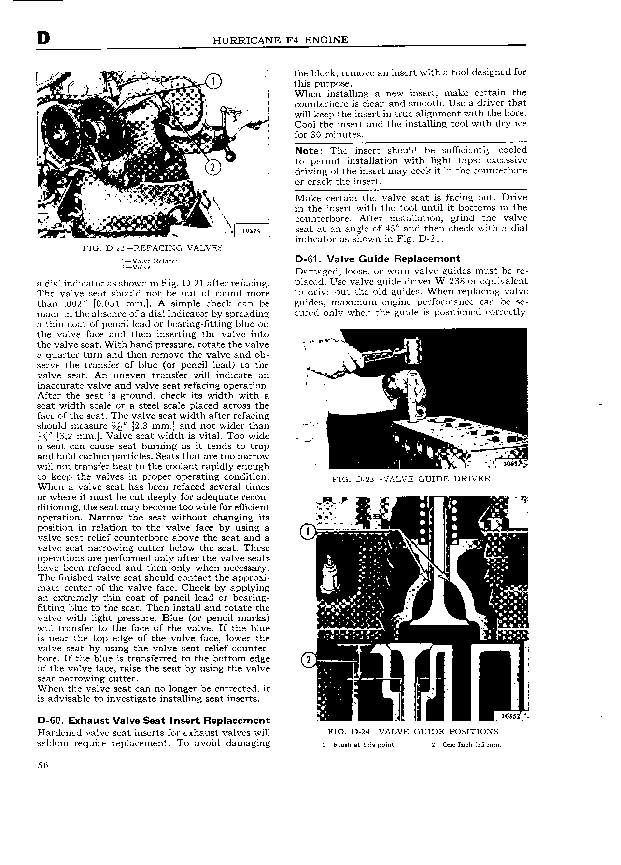
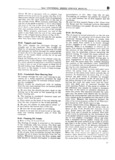
f A the block remove an insert with a tool designed for s i 0 this i ri S 3 When installing a new insert make certain tht iliii I il Q A counterbore is clean and smooth Use a driver that L J ilil Tg 5 E f l will keep the insert in true alignment with the bore i F Cool the insert and the installing tool with dry ice k for 30 minutes i t A ab Note The insert should be sufficiently cooled ii ii V i l to permit installation with light taps excessive 5 L V Q A 0 driving of the insert may cock it in the counterbore 1i Y C i or crack the insert V S l i V V Make certain the valve seat is facing out Dr1ve I j in the insert with the tool until it bottoms in the 5 D j eounterbore After installation grind the valve I seat at an angle of 450 and then check with a dial 4 V V A D 21 FIG D 22 WREFACING VALVES iavaive Refacey D 61 Valve Guide Replacement Zwvam Damaged loose or worn valve guides must be re a dial indicator as shown in Fig D 2l after refacing DI3 d U valve gIIId driver W 238 OI luIV3 IIt The Valve Seat Shguld not be Out Of rgund more to drive out the old guides When replacing valve than 0O2 0 051 mm A simple check can be guid S maximum gI D YI0I m can be S made in the absence ofa dial indicator by spreading cured only when th guldfi IS P0 I 0 d COIWCUY a thin coat of pencil lead or bearing fitting blue on the valve face and then inserting the valve into A the valve seat With hand pressure rotate the valve V n a quarter turn and then remove the valve and ob I serve the transfer of blue or pencil lead to the l 5 I valve seat An uneven transfer will indicate an f i inaccurate valve and valve seat refacing operation jif After the seat is ground check its width with a V u seat width scale or a steel scale placed across the face of the seat The valve seat width after refacing F 1 i V should measure 2 3 mm and not wider than rf i f L a L lg 3 2 mm Valve seat width is vital Too wide se t a seat can cause seat burning as it tends to trap 2 azv and hold carbon particles Seats that are too narrow will not transfer heat to the coolant rapidly enough it I to keep the valves in proper operating condition FIG D 23 VALVE GUIDE DRIVER When a valve seat has been refaced several times or where it must be cut deeply for adequate recon J J ditioning the seat may become too wide for efficient E tg operation Narrow the seat without changing its 2 0 ii position in relation to the valve face by using a 0 am V U i i l valve seat relief counterbore above the seat and a T i i i i ii iii Simi i i j i i Q valve seat narrowing cutter below the seat These i N operations are performed only after the valve seats i I i i Ri have been refaced and then only when necessary gjj The finished valve seat should contact the approxi i mate center of the valve face Qheck by applying li V E g V an extremely thin coat of pencil lead or bearing Z 2f i j jj g f j1 fitting blue to the seat Then install and rotate the lli valve with light pressure Blue or pencil marks V 2 will transfer to the face of the valve If the blue I V is near the top edge of the valve face lower the i r i i E valve seat by using the valve seat relief counter r fi bore If the blue is transferred to the bottom edge 0 of the valve face raise the seat by using the valve V I seat narrowing cutter When the valve seat can no longer be corrected it I i i is advisable to investigate installing seat inserts J J D 60 Exhaust Valve Seat Insert Replacement E Hardened valve seat inserts for exhaust valves will FIG D 24 rVAI VE GUIDE POSITIONS seldom require replacement To avoid damaging ia Fiush at this perm 2 one meh rzs mm 56