Ford Parts Wiki | GM Parts Wiki
Home | Search | Browse
Prev

 Next
Next
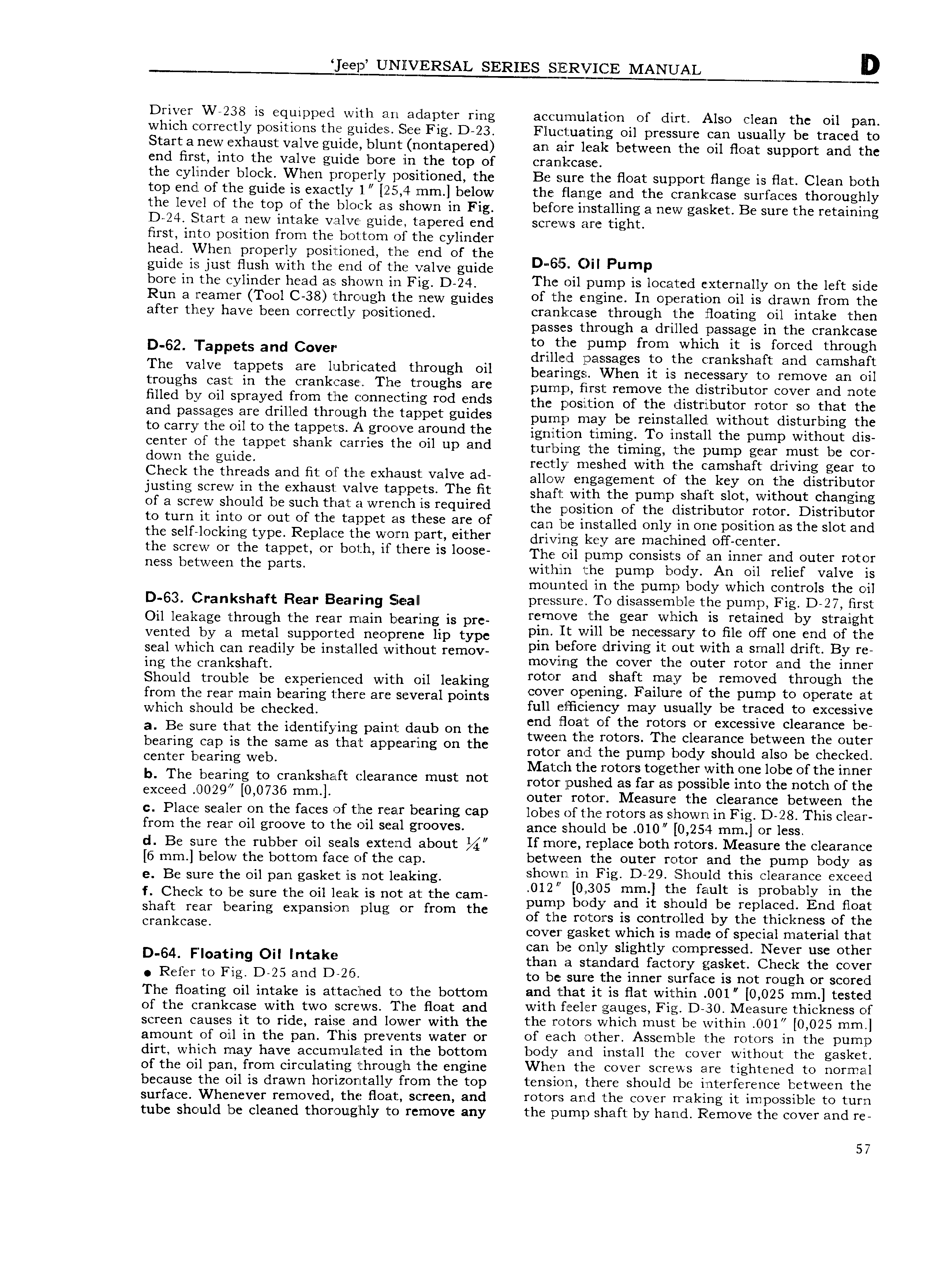
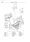
kE Ul llVERSAL SERIES SZIERVICE MANUAL D Driver W 238 is equipped with an adapter ring accumulation of dirt Also clean the oil pan which correctly positions the guides See Fig D 23 Flu tuatin g oil pressure can usually be traced to Startanew exhaust valve guide blunt nontapered an air leak between the oil float support and the end flrst into the valve guide bore in the top of cranll case the cylinder block When properly positioned the Be sure the float support flange is flat Clean both top end of the guide is exactly 1 1255 4 mm below the flange and the crankcase surfaces thoroughly the level of the top of the block a s shown in Fig before installing a new gasket Be sure the retaining iD 24 Start a new intake valve guide tapered end screws are tight first into position from the bottom of the cylinder head VVhen properly positioned the end of the I guide is just flush with the end of the valve guide D 6l O Pump bore in the cylinder head as g Wn in Fig D 24 The oil pump is located exterr1all y on the left side Run g fganjgy TOO lthfcyugh hc ijlcw guides of llllllli H gll lC lu OpCfI 3 tlO1 1 is lI 3WI 1 fI OI1 1 tlT1C after thley have been correctly positloned crankcase through the floating oil intake then passes through a drilled passage in the crankcase to the pump from which it is forced through D 62 rappets and Cover drilletl passages to the crankshaft and camshaft The V uVe rappers are l b t l fllr sh Ou bearings VVhen it is necessary to remove an oil twushs cast lh the el ahkease The el Oughs are pump first remove the distributor cover and note filled by ll sprayed fwm the s wd ds the j1 OSl lZlCl1 1 or the tnltrlllolltor rotor so that lZl1C and passages are drilled through the iapp f g l1d S purrip may be reinstalled without disturbing the lie carry the Ou te thc t3DPel s A gYe e Ve afeuhd the ignition timing To install the pump without dis center of the tappct shank Ct1f1 l S l l l Oll Llp and tulgllying the timi g the purnp gear must be jor uewh the guude rectly meshed with the camshaft driving gear to Check the threads and fit ofthe exhaust valve ad anew engagement Of the key en the distributel lustlhg sel eW lh the exhaust Valve l 3 ls Pe ts Th ht shaft with the pump shaft slot without changing Of 3 Screw Sll ld be Such that 3 Wfeheh ls required the position of the distributor rotor Distributor to tum it hue OY out Of the taupet as these are Of can be installed only in one position as the slot and t l 1 S ll lOCl lIlg type R pl3 ZC UIC W OZl H Daft either dl ivfing kggy are mgchingd Off j n1 f the seYe W OY the tappee OY hethl ui there is lOOse The oil pump consists of an inner and outer rotor hess heliweeh the Parts withfin the pump body An oil relief valve is mounted in the pump body which controls the oil 53 jrankshaft Reap Bearing e a pressure To disassernble the pump Fig D 27 first Oil leakage through the rear main bearing is pre Nlmclvc lhh gear Welch ls retaescl by strmght Vented by El metal Supported nwpmnc lip type pin It w1l l be necessary to file off one end ofthe seal which ooo readily be installed without lomov vm l l f f l v1 g t with Small dm By moving the cover the outer rotor and the inner ing the ci ankshaft Should trouble be experienced with oil leaking t ml shaft malv bs moved thwugh thc from the rear main bearing there are several points Covcll Opllmmg Fallum Ol the pump to Operate aft which Should be checked full efllclerncy may usually be traced to excessive B that the idcntifwmg paint daub On the end float of the rotors or excessive clearance be a 6 Sure y h I h tween the rotors The clearance between the outer bcarmg Cap ls the Same as t lat app B ar mg on t C rotor and the pump body should also be checked Center hem mg Web Match the rotors together with one lobe of the inlner b The heahlhg te erahksheuit eleerahee must het rotor jpushed as far as possible into the notch of the exeeed h029 0 0736 mm l outer rotor Measure the clearance between the c Place sealer on the faces of the rear bearing cap lobes of the rotors as shown in Fig D 128 This clear from the rear oil groove to the oil seal grooves ance should be 010 0 254 mm or less d Be sure the rubber oil seals extend about If ITlO1Z C replace both rotors Measure the clearance 6 mm below the bottom face of th e cap between the outer rotor and the pump body as ei BC Sure the Oil pan gasket is not 1 ak mg shown in Fig D 29 E hould this clearance exceed f Check to be sure the oil lerlk is not at the cam 012 A 0305 mmf the fault ls probably m the h pump body and it should be replaced End float Shaft rear bcarmg expanswm plus or from t C of the rotors is controlled by the thickness of the cl ank aS cover gasket which is made of special material that can be only slightly compressed Never use other D e4 Fl af s O Intake than a standard factory gasket Check the cover Refer to Fig D 25 Glld D 26 to be sure the inner surface is not rough or scored The floating oil intake is attached to the bottom and that it is flat within 0Ol 0 025 mm tested of the crankcase with two screws The float and with l l l EI gauges Fig D 30 Measure thickness of screen causes it to ride raise and lower with the the rotors which must be within 0O1 0 025 mm amount of oil in the pan This prevents water or of each other Assem ble the rotors in the pump dirt which may have accumulated llfl the bottom body and install the cover without the gasket of the oil pan from circulating through the engine When the cover screws are tightened to norimal because the oil is drawn horizontally from the top tension there should be interference between the surface Whenever removed the float screen and rotors an d the cover rraking it impossible to turn tube should be cleaned thoroughly to remove any the pump shaft by hand Remove the cover and re 57

 Next
Next