Ford Parts Wiki | GM Parts Wiki
Home | Search | Browse
Prev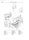
 Next
Next
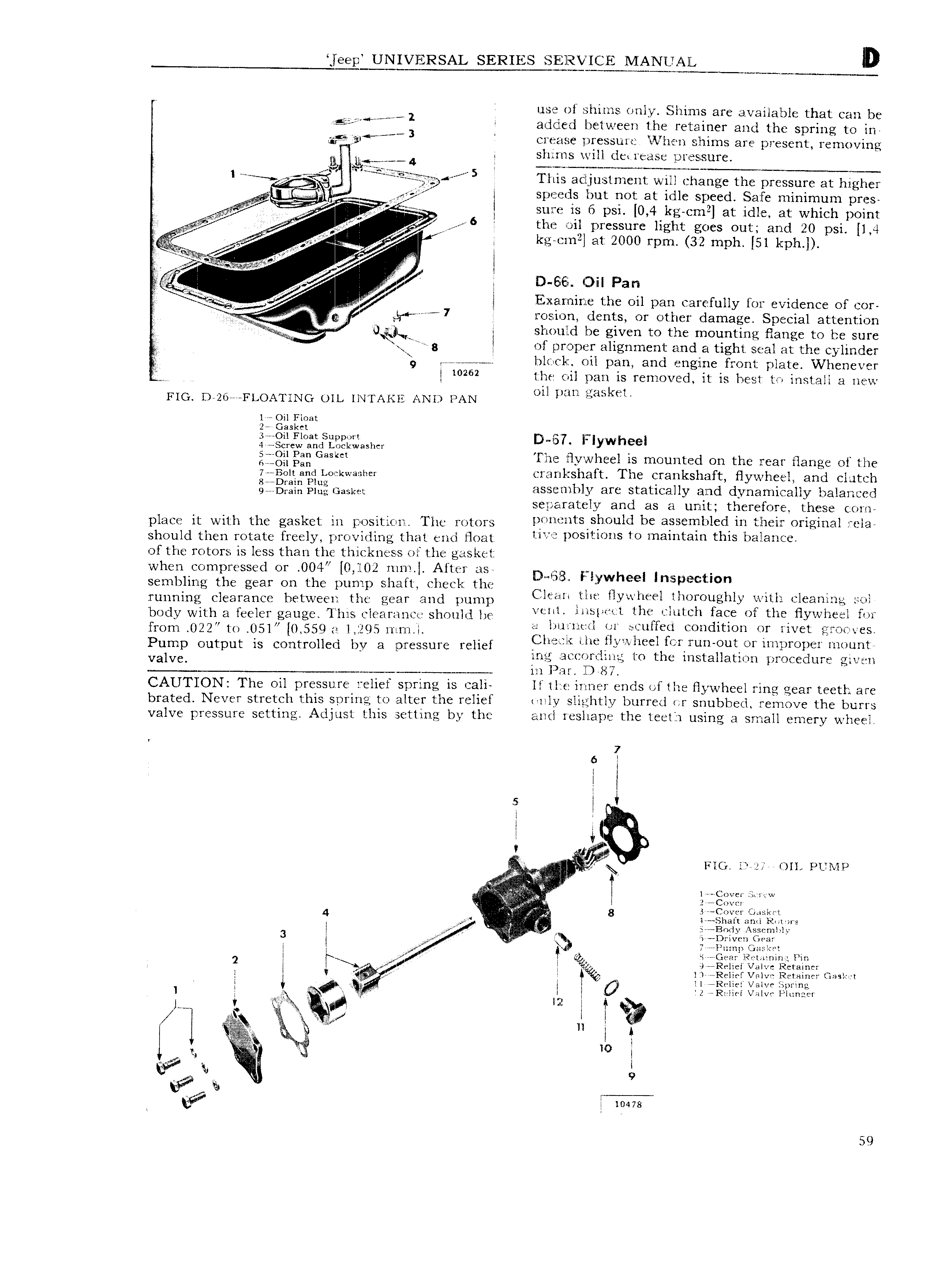
ee p UNIVERSAL SERIES SE ll2 ICE l IANUAL lb 2 i use of shims only Slhiznis are availah e r V V 1 M Z t at can be adued between the retainer and the s rin 3 p g to 1n 3 eieae se pressure Y Vll i Il shims are present removing 1 s ll X llS will der rease pressure H1 1l 4 av sg mtr i T r r t r iTt9 S g This acl j 11 stment will change the pressure at higher v i spemls but not at idle speed Safe minimum pres 5 SlZlK T is In psi 0 4 kg cm at idle at which point lg lz i 2 6 the oil pressure light goes out and 20 psi O we kg ein at 2000 rpm 32 mph Sl l ph I iw s K eb Se 1 g VV gi i D Ei l Olll Pan kw l E V v z p l Xfnlmlmfi l h Oll pim Carefully for evidence of enr g V L El r 7 rcrsmon dents or other damage Special attention gg G Jl 5h j 1 1l d be given to the IT1OLlI1t1Ilg HHHQC to lbf SUYC Z g of proper alignment and a tight seal at the cylinder I 9 7 hlci c l oil pan and engine front plate Whenever l 0262 the oil pan is removed it is hest to install a new Fm D 26 aa FLOATlNG ou 1 1 1lrA xi AND PAN mal mu gHSk il lee gil Float 2 askrt 3 r V O l Fl s 4 V Stircwojrid Iliiolglxiiriznsher D D7 I gig gg Gaskm Fne flywheel is mounteci on the rear flange of the 7 1301 gig Loekwasher CX lfIl CSh2Ell t The crankshaft flywheel and clutch QQDQQQQ Egg GZSW assembly are statically and dynamically balanced sejgcarately and as a unit therefore these com place it with the gasket in pOSitj m ThC mmm pn nentsVshould be 3 5E3 1l lil l l d 1Iil their original rela should then rotate freely providing that end float l l l O t S TO lnimmiin this l il81 1 of the rotors is less than the thickness of the gasket when compressed or 004 0 102 ilIl1 l l After i D l l f l 1 sembling the gear on the pump shaft cheek the fg flwheeil I 15p mt n j u ping Clggygncg fygtwegyi hc gear and punlp Cltiflll Jill H YV ll l l llOX Ol1glll y Evlllfl Tl 3n3 jail b0dy with a feeler auge This rlea r a11et should he l l L lh 0 ll lill BCG Ol thr flywheel mr g from 022 to 05l 0 559 as 1 1295 mm i l i F S d O i f Pump Output is Cammucd by 3 m SSul relief l l fi Tl a l1ell jywr1ee1f 1i r rt1r1 out orimproper mount valva ing acztzorclxne to the installation procedure givscn m s in Pa 1 li 2 CAUTION The oil pressure relief spring is cali lf llve inner ends of the flywheel ring gear teeth are brated Never streteh this spring to alter the relief i1lgy slightly hurred or snubbed remove the bums valve pressure setting Adjust this setting by the and reshape the teeth using a small emery wheel 7 6 l 1 l l l l 5 l Q l il Sfl r 1 Q FIG SM1 OIL PUMP ii a g 5 7 C r Gt sket 4 Ja ff 1 8 1 s1ii frI ri1 s r M E 3 F WN j I e B0cly Assenuhly 4 af yy t Dr G ar l W 1r Il l ii1i 1 Gz1 k it I x ar l wh 1 1n 2 l 4 HQWG 9 R l1el Vallvhulhetaincr l V i ll Relief Valve Retainer Gaslrst 1 sian 1 1 v11 s l O 2 eRi li l iilxiii l l s rii2er L Y ei l 1 l Q r l i 2 g 1 t f l s w a l M l xy 1 s V mus 59