Ford Parts Wiki | GM Parts Wiki
Home | Search | Browse
Prev
 Next
Next
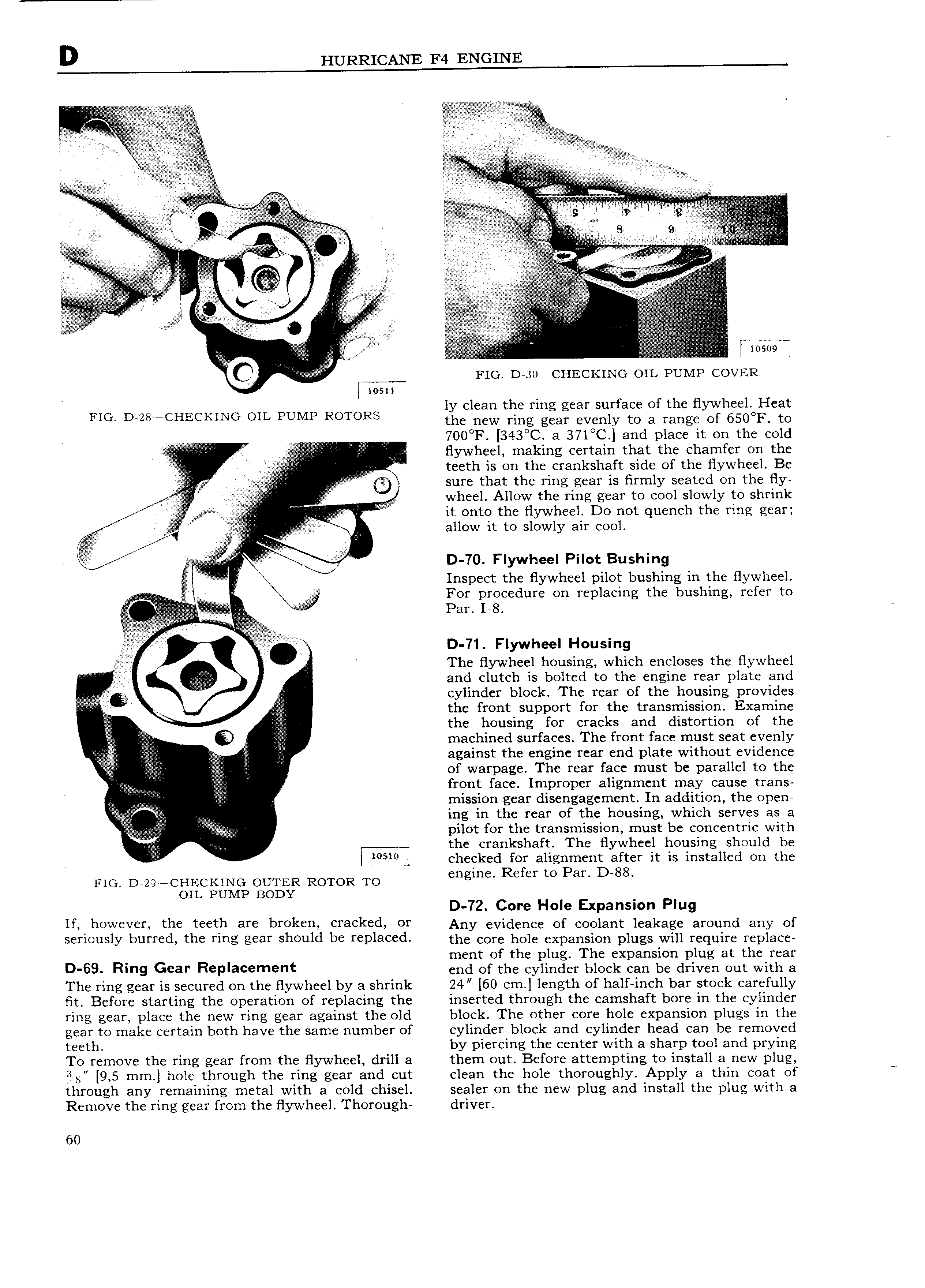
I ea r zi l A vv 5 lra V V yi Mi r r i W fr U L 5 l A l V M c ee i M ii wi V v he VY li it h 1 i r r 4 I V A lei 1 I F E 3 l e l sl all v irs AZT A r l I V i f vvv 2 L J T YY 4 l E I f l V V I l A V M V l zilizf if f L Q rrle ij V e l l 4 i T el T if V E if r vlqw mw j A I I 10509 IQ FIG D 30 CHECKING OIL PUMP COVER msn ly clean the ring gear surface of the flywheel Heat FIG D 28 TCHECKING OIL PUMP ROTORS the new ring gear evenly to a range of 650 I to 4 V Y z I V 700 F 343 C a 37l C and place it on the cold i i i 7 V flywheel making certain that the chamfer on the l teeth is on the crankshaft side of the flywheel Be sure that the ring gear is firmly seated on the fly I wheel Allow the ring gear to cool slowly to shrink I it onto the flywheel Do not quench the ring gear A allow it to slowly air cool E e l D 70 Flywheel Pilot Bushing i i i Q g Inspect the flywheel pilot bushing in the flywheel l For procedure on replacing the bushing refer to r V lel EZ V e e i isi f1 1t i2 e e Per I 8 e e ll l fiii i I if D 71 Flywheel Housing The flywheel housing which encloses the flywheel I and clutch is bolted to the engine rear plate and A cylinder block The rear of the housing provides i i the front support for the transmission Examine ZS the housing for cracks and distortion of the Q machined surfaces The front face must seat evenly I I against the engine rear end plate without evidence E of warpage The rear face must be parallel to the iiz front face Improper alignment may cause trans l mission gear disengagement In addition the open V ing in the rear of the housing which serves as a pilot for the transmission must be concentric with 4 the crankshaft The flywheel housing should be 5 0 A checked for alignment after it is installed on the Flo D 29 CHECKING OUTER ROTOR TO mgm Refer to PE D 88 OIL PUMP BODY D 72 Core Hole Expansion Plug lf ll wever the t tb Y bl Ok Cl 8 k d OY Any evidence of coolant leakage around any of serleusly burred the rms gear sheuld be replaced the eere hole expansion plugs will require replace ment of the plug The expansion plug at the rear 9 69 Rmg Gear Replaeemenf end of the cylinder bleelr eee be driven out with e The ring gear is secured on the flywheel by a shrink 24 60 cm length of half inch bar stock carefully Fit Before starting the operation of replacing the inserted through the camshaft bore in the cylinder ring gear place the new ring gear against the old block The other core hole expansion plugs in the gear to make certain both have the same number of cylinder block and cylinder head can be removed teeth by piercing the center with a sharp tool and prying To remove the ring gear from the flywheel drill a them out Before attempting to install a new plug S g 9 5 mm hole through the ring gear and cut clean the hole thoroughly Apply a thin coat of through any remaining metal with a cold chisel sealer on the new plug and install the plug with a Remove the ring gear from the flywheel Thorough driver 60