Ford Parts Wiki | GM Parts Wiki
Home | Search | Browse
Prev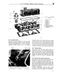
 Next
Next
994757
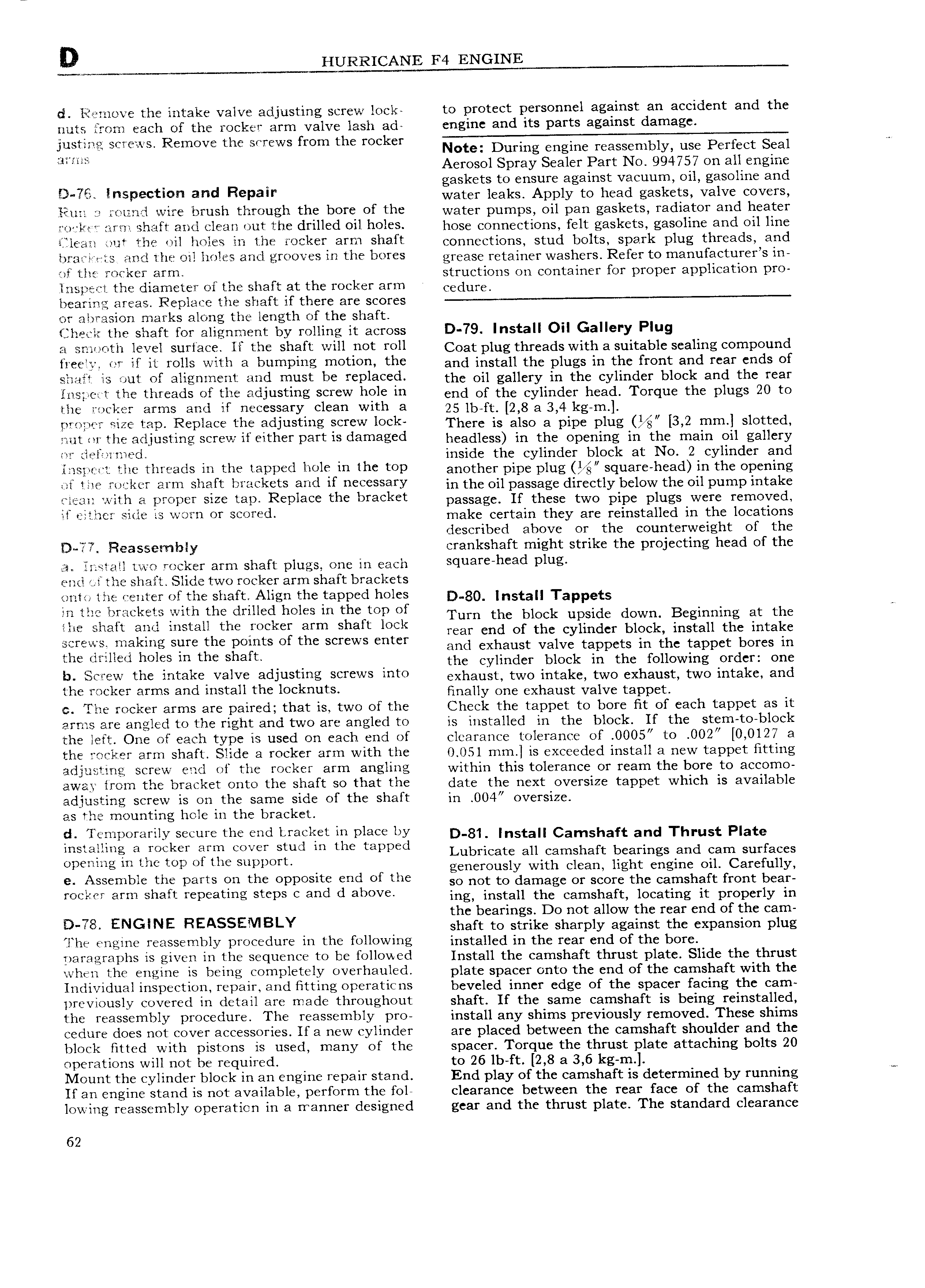
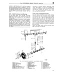
D HURRICANE F4 ENGINE ci l l3r E lIlO the intake valve adjusting screw lock to protect personnel against an accident and the nuts from each of the rocker arm valve lash ad engine and its parts against damage screws Remove the screws from the rocker l im Aerosol Spray Sealer Part No 994757 on all engine gaskets to ensure against vacuum oil gasoline and i f l P tl and Repalr water leaks Apply to head gaskets valve covers Yl un r i n i wire brush through the bore of the water pumps Oil pan gaskets radiator and heater r ia l t arrzi shaft and clean out the drilled oil holes hgge eeuueetighs felt gaskets gasoline and oil line iiliean out the nil holes in the rocker arm shaft eohueetlerrs stuel bglts spark plug threads and brari n ts and ihe oil holes and grooves in the bores grease retalrrer washers Rgfgf to rrraoufaetureys lr if l l F l Fl i Nm structions on container for proper application pro inspect the diameter of the shaft at the rocker arm eetlure bearing areas Replace the shaft if there are scores or abrasion marks along the length of the shaft jhecir the shaft for alignment by rolling it across D 79 Install Oil Gallery Plug a smooth level surface ll the shaft will not roll Coat plug threads with asultable scaling Cgmpgund l l Z W if ll r 11 Wllh 3 bumping mOtl0 thf and install the plugs in the front and rear ends of sti ii out of alignment and must be replaced the oll gallery in the eyllrrder blgek and the rear irispc t the threads of the adjusting screw hole in errtl of the cylinder heael Torque the plugs Q te the rocker arms and if necessary clean with a 25 lb ft 2 8 a3 4 kg m rimlwq r size tap Replace the adjustiilg SCYSW lock There is also a pipe plug 3 2 mm Sl0 it l nut or the adjusting screw if either part is damaged headless ln the openlug in the rrralrr oll gallery W l l i l m l inside the cylinder block at No 2 cylinder and iElS l Zl lQ UIC fllf 2lClS lll tll l Zipp Cl llOl l1 1 the top arlothgy SquaI h ad in the Opel llng win l T U jl CT 2lI IIl shaft l l 3 Ck tS 3 Ild DCC SHI y ln thc passage directly below the punjp intake with El proper size tap Replace the bracket passage If these two pipe plugs were remoyetl ll i l l li Sli W Wfym OY S 9V d make certain they are reinstalled in the locations described above or the counterweight of the lD i 7 Fieassembly crankshaft might strike the projecting head of the el install two rocker arm shaft plugs one in each luaY h 3d Plug enti ef the shaft Slide two rocker arm shaft brackets onto the center of the shaft Align the tapped holes g lnstall Tappets the brackets with the drilled holes in the top of Turn the block upside down Beginning at the rne shaft and install the rocker arm shaft lock may end Of the Cylinder block install the intake screws making sure the points of the screws enter and exhaust Valve tappcts in the tappet bores in the lrllilucd hows m the Shaft the cylinder block in the following order one b Screw the intake valve adjusting screws into exllausp two lptake two cXhaust two lptake and the rocker arms and install the locknuts lrrpally one exhaust Valve tappet e The rocker arms are paired that is two of the Check the tappet to bore fit of each tappet as it arms are angled to the right and two are angled to is installed in the block If the stem to block the left One of each type is used on each end of clearance tolerance of 0005 to 002 0 0127 a the rocker arm shaft Slide a rocker arm with the 0 051 mm is exceeded install a new tappet fitting adjusting screw end of the rocker arm angling within this tolerance or ream the bore to accomo away from the bracket onto the shaft so that the date the next oversize tappet which is available adjusting screw is on the same side of the shaft in 004 oversize as the mounting hole in the bracket d Temporarily secure the end Lracket in place by D g l Install Camshaft and Thrust plate lnstallmg 3 Seeker arm COV r stud m the mppcd Lubricate all camshaft bearings and cam surfaces Urges m Ulcfop Of the SuppOrt generously with clean light engine oil Carefully 9 fxSS mbl the Wills Qu the OPPOSKC Cmd Of the so not to damage or score the camshaft front bear rocl xer arm shaft repeating steps c and d above rpg lpstall the Camshaft lppatlpg lr properly lp the bearings Do not allow the rear end of the cam D 7S E NGlNE REASSEMBI Y shaft to strike sharply against the expansion plug The engine reassembly procedure in the following installed in the rear end of the bore paragraphs is given in the sequence to be followed Install the camshaft thrust plate Slide the thrust when the engine is being completely overhauled plate spacer onto the end of the camshaft with the Individual inspection repair and Fitting operaticns beveled inner edge of the spacer facing the cam previously covered in detail are made throughout shaft If the same camshaft is being reinstalled the reassembly procedure The reassembly pro install any shims previously removed These shims cedure does not cover accessories If a new cylinder are placed between the camshaft shoulder and the block Htted with pistons is used many of the spacer Torque the thrust plate attaching bolts 20 operations will not be required to 26 lb ft 2 8 a 3 6 kg m Mount the cylinder block in an engine repair stand End play of the camshaft is determined by running W If an engine stand is not available perform the fol clearance between the rear face of the camshaft lowing reassembly operation in a rranner designed gear and the thrust plate The standard clearance 62