Ford Parts Wiki | GM Parts Wiki
Home | Search | Browse
Prev
 Next
Next
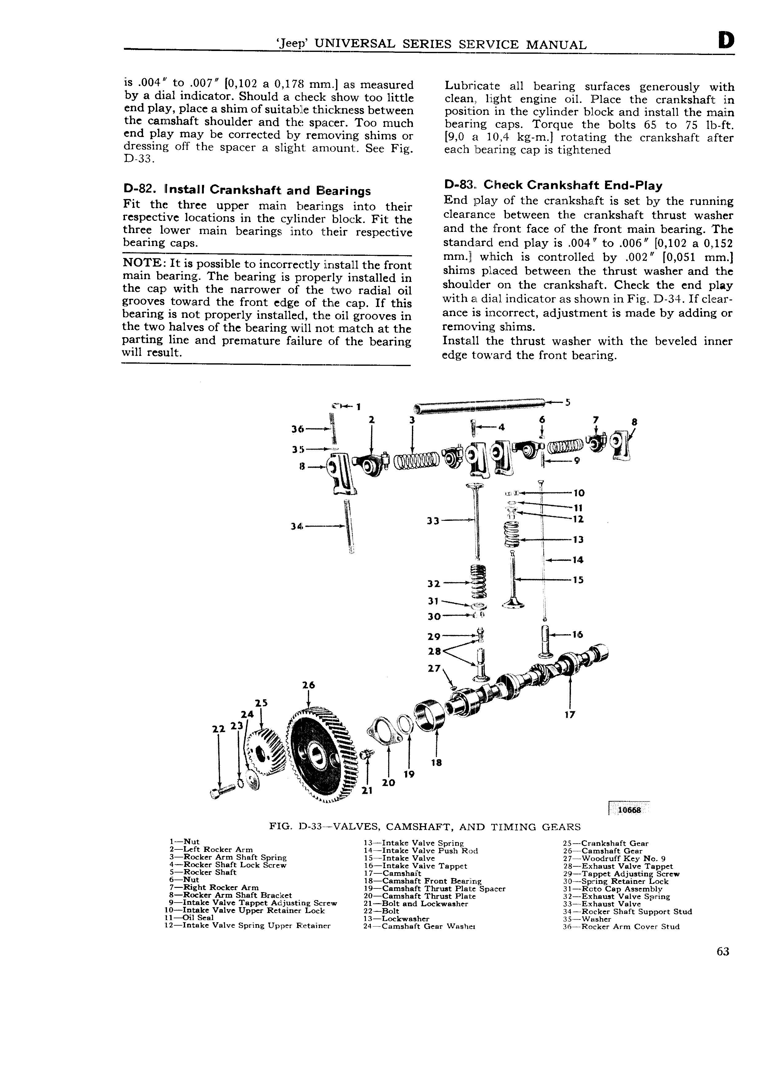
kgf UQEQXERSAL SERIES MANUAL D is 004l to 007 0 1 02 a 0 178 min as measured Lubzricate all bearing surfaces generously with by a dial indicator Should a checl show too little cleant light engine oil Place the crankshaft in end play place a shim of suitable thicckzness between position in the c linder block and install the main 4 Y the camshaft shoulder and the spacer Too much bearing caps Torque the bolts 65 to 75 lb ft end play may be corrected by removing shims or 9 0 El 10 4 kg m rotating the crankshaft after ge ing off the spacer a slight arnoun1 See Fig each lbeazririg cap is tightened D 82 Ilnstall Crankshaft amd Elearilngs E 3 L 1 tE 1 j i End Play h Fit the three upper main bearings into their In P 3 i tt e cri tlf1f r bit e runiilnlg respective locations in the cylinder block Fit the C caralncj jc Ween gc Gan S a t t ms wa ui three lower main bearings into their respective and the mont acc Ot the fmnt mam b armg Thc bearing caps standard end play is 004 to 006 0 102 a 0 152 1 which is controlled by 002 O 051 mm NOTE M Itds posslblc toinccincdly mstqm thc from shims placed between the thrust washer and the mam bearing The bearing is properly installed in ho H 1 th k h ft Ch k th d 1 the cap with the narrower of the two radial oil S u lc O c cmu a ci C cn p ay gl OOVCS toward the mnt edge of the Cap If this with at dial indicator shown in Fig D 34 If cl ea1 b fi g is not properly installed thro oil grooves in ls lmccvfrcct adjustment is made by adding or the two halves of the bearing will not match at the Ycmovmg hlmS partmg line and premature failure of the bearing Install the thrust washer with the beveled inner will result edge toward the front bearing WH 1 r fT Y t 4 ra v 5 i 2 zz at 6 1 8 aes i E E 3Zi 9 li 9 ll 8 g4 QP vt l ff a B qi il r I0 tl l 1 at l 3 3 ag 13 I 1 4 32 is 31 30 1 ti Q A 28 r Q 5 27 W AK H 16 7 ass 15 24 zz 23 4 V Q 5 EQ Lg s i eg Qi Q W afi s Ra e Q A 55 vv qw r lk X i 21 2 0 e F W mess FIG D 33 V All VES CAMSHAFT AND Tlll ING GEARS 1 Nut 134Intake Valve Spring 25 rCI IlIli S 1BfC Gear 2 Le ft Rocker Arm 14 Intal e Valve Push Rod 2 5 Camshaft Gear 3 R0cker Arm Shaft Spring l5 Intake Valve 27 W0odruff Key No 9 g gpgllier 2 1 Lock Screw 1 antak V alve Tappet i xhau tA galv iTa pet Cf 8 BIDS BI U SPDC j S ng CYCW i i t Rocker Arm I Z E1 Iii i3 3 B a Zl p l Sl i Z i i LZ L k 8 R0cker Arm Shaft Bracket 20 Camshaft Thrust Plate 3Z Exhaust Valve Spring 4 9 Intakc Valve Tappet Adjusting Screw 21 Bolt and Lockwasher 33 Exhaust Valve Hlgglgzyalve Upper Retainer Lock iizgggcwashc Shaft Support Stud l2 Intake Valve Spring Upper Retainer 24 Camshaft Gear Washer 36 eRocker Arm Cover Stud 63