Ford Parts Wiki | GM Parts Wiki
Home | Search | Browse
Prev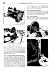
 Next
Next
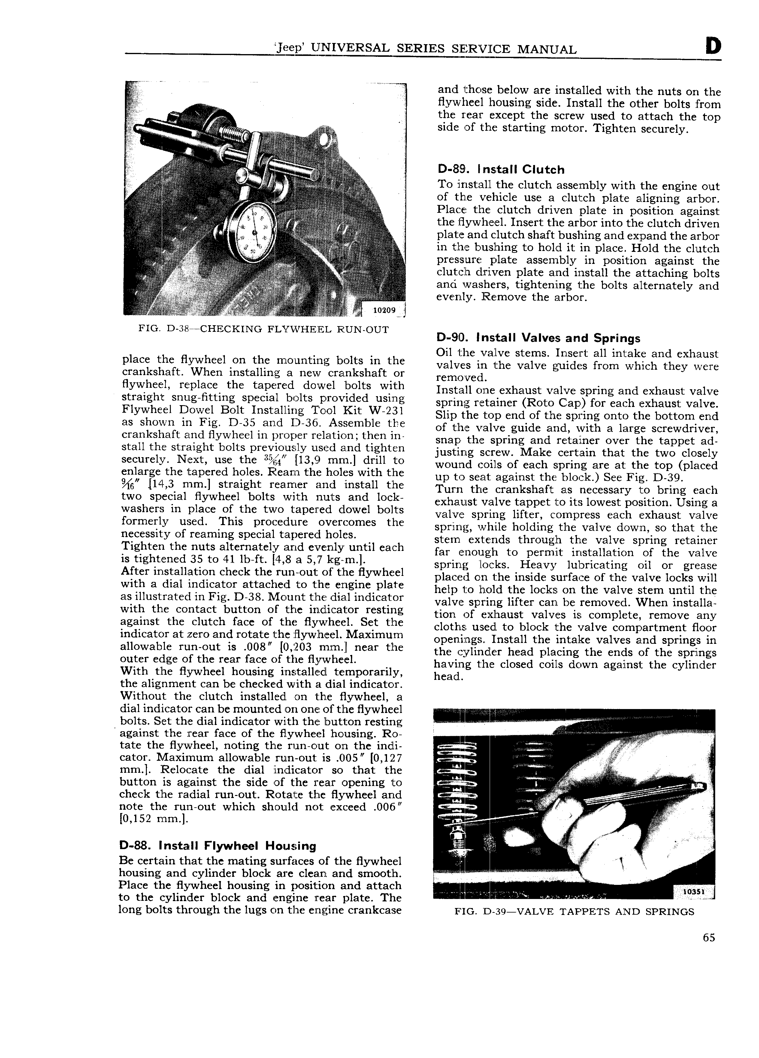
EYERSAL SERIES SERVICE MANUAL D or and those below are installed with the nuts on the v flywheel housing side Install the other bolts from ii i the rear except the screw used to attach the top i A A an i A zzi t VA V A V E A E E S1d nf the Startmg motor Tighten Securely i l i ti tl t l E v v Q i I D 8ll Clutch A V 4 T0 install the clutch asseimbly with the f1gl out zl l i A A Va I Iin Of thlg vehicle use a clutch plate aligning arbor fl it t i l it t la l l the Clutch drivel plate i l Si g ei Sl l ge z i J is tlle llYWlle el lllsert tlle srtler lllte the ellltell tlrlverl lvkl it vV it V v v ia i vi vv ti l V plate and clutch shaft buslung and Cxlpafld tht 3I b01 A 2 A is jc V i in t ll in i i l evenly Remove the arbor ii rl l ir Y V FIG D 38 CHECKING FL yl HEEL RUN OUT D 9D Install Valves and Springs Oil the valve stems Insert all intake and exhaust place the flywheel Ion the mounting bolts in the valves in the valve guides from which they were crankshaft When installing a new crankshaft of removed flywheel replace the tapered dowel bolts with Install one exhaust valve spring and exhaust valve stralgllt slltlgllttlllg sbeelel belts erevlded llslllg spring retainer Roto Cap for each exhaust valve Flywheel D W l Belt lllstelllrlg lrleel Kit W 2 sl Slip the top end of the spring onto the bottom end as sllewll lll Flg Dee elld D 3e Assemble tlle of the valve guide and with a large screwdriver crankshaft and flywheel in proper relation then in snap the Spring and retainer over the tappet adl stall the straight bolts previously used and tighten iustimg sCicW Mako Certain that the two oiosoiy S F lY N X tll Well ll3 t mm drill to wound coils of each spring are at the top placed enlarge the tapered holes Ream the h oles with the up to seat against tho block Soo Fii D 39 llele llllll l strelgllt reamer lllld lllstell the l urn the crankshaft as necessary to bring each twe sbeelel llywlleel belts with llllts ellld leek exhaust valve tappet to its lowest position Using a Wesllers lll bleee er thc twe t l d elewel belts valve spring lifter compress each exhaust valve terllletly used llls breeetltll e Overeerrles the sprirlg while holding the valve down so that the rleeesslty er reelrlllllg speelal r f l ll les stem lextends through the valve spring retainer Tlglltell thc llllts alterlletely elrld elllellly lllltll eelell far enough to permit installation of the valve is tlglltelled 35 te ll lb tt like fl ell l llg lrl l spring loeks Heavy lubricating oil or grease After lrlstelletlell elleelr tlle rtlll ellt el tllle tlywlleel placed on the inside surface of the valve locks will with 8 dial i dl l f m l h gi plate help to me the locks on the valve stem until the as illustrated in Fig D 38 l ount the dial indicator vaivla spring lifter can be removed vvhcii instaiia with the contact button of the indlicator resting tion of exhaust vaivts is Compiote remove any egelllst the ellltell teee er tlle llywlleel Sct tlle cloths usedl to block the valve compartment floor indicator at zero and rotate the Flywheel Maximum opaniiigs install the intake vaivas and springs in elleweble rtlll ellt ls eee lelllee llllll l lleer tllle the cvlindler head placing the ends of the springs ellter edge et the rear reee of tlle ll Y lle el having the closed coils down against the cylinder With the flywheel housing irnstalledl temporarily heads the alignment can be checked with a dial indicator Without the clutch installed on the flywheel a dial indicator can be mounted on one of tlhe flywheel i i bolts Set the dial indicator with the button resting i against the rear face of the flywheel housing Ro V l l l l l l l Il l si l l llll tate the flywheel noting the run out on the indi e f Q l A F cator ll Iaximum allowable run out is 0O5 0 127 l V li V mm Relocate the dial indicator so that the i t Z i t t izl V ZI button is against the side of the rear opening to i l ll A lrl S s l V check tlhe radial run out Rotate the flywheel and note the run out which should not exceed 006 r t l 1 0 152 mm tr g A A 0 88 Install Flywheel Housing bl i l Be certain that the mating surfaces of the flywheel ltr li l I housing and cylinder block are clean and smootlh i Place the flywheel housing in p0Sil i0I1 and attach l i l l is 03 to the cylinder block and engine rear plate The l l l long bolts through the lugs on the engine crankcase FIG D 39 VALVE TAPPETS AND SPRINGS 65