Ford Parts Wiki | GM Parts Wiki
Home | Search | Browse
Prev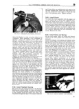
 Next
Next
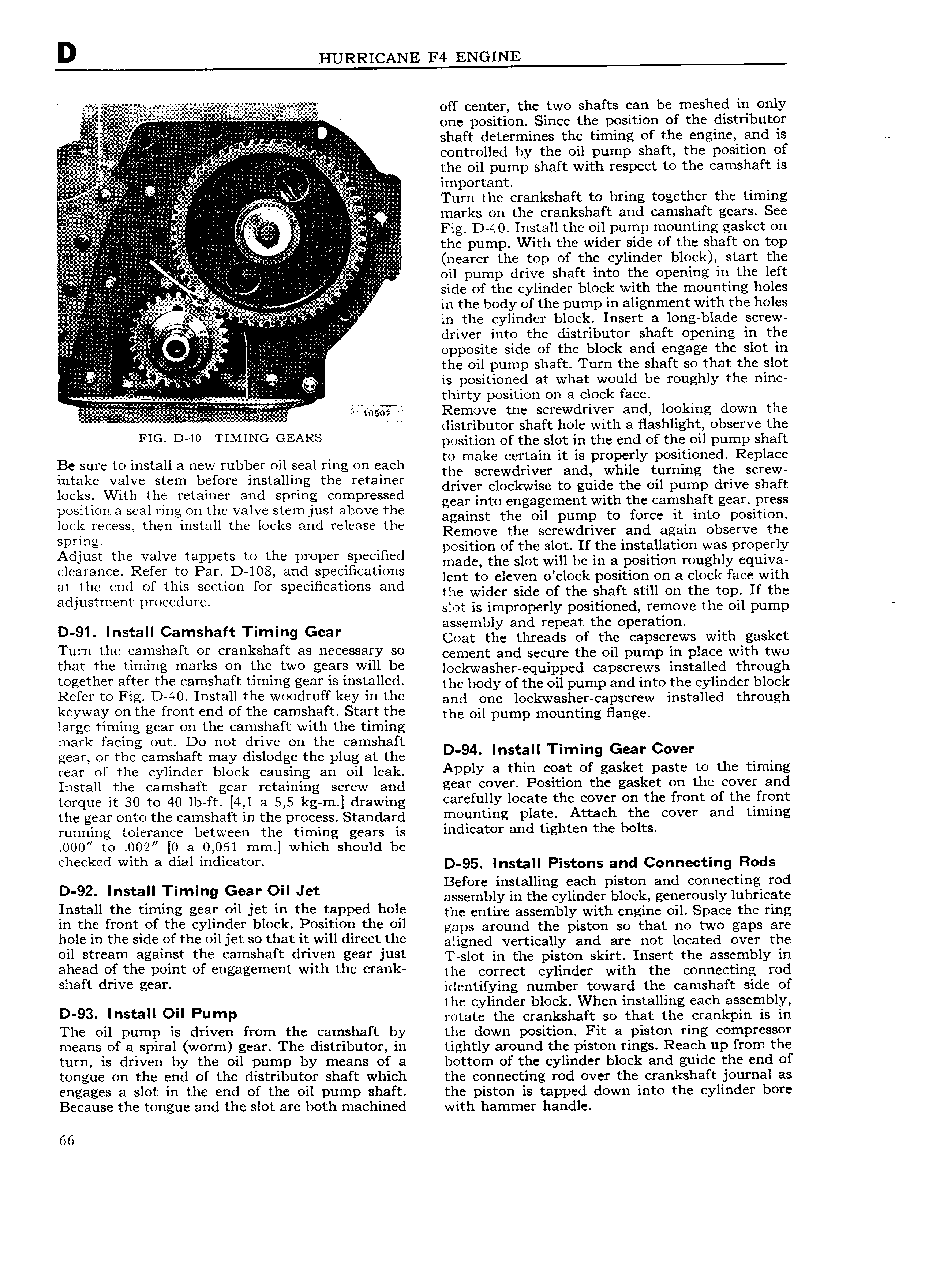
l off center the two shafts can be meshed in only ii i m one position Since the position of the distributor LJ V shaft determines the timing of the eng1ne and 1S v i iii i controlled by the oil pump shaft the posltlon of the oil pump shaft with respect to the camshaft 1S l ii ia i V lE iml ertant i i o i Turn the crankshaft to bring together the timing r marks on the crankshaft and camshaft gears See V it Fig D 40 Install the oil pump mounting gasket on the pump With the wider side of the shaft on top rfi ii i i r z ii nearer the top of the cylinder block start the t i g oil pump drive shaft into the opening in the left V it i i r TQ side of the cylinder block with the mounting holes H lllrvvl X V in the body of the pump IH alignment with the holes i in the cylinder block Insert a long blade screw driver into the distributor shaft opening ln the i G ii e opposite side of the bleek anti engage the slot in V V r i l the oil pump shaft Turn the shaft so that the slot i i Ei eire Q is positioned at what would be roughly the nine e e X N VVV thirty position on a clock face l i it lnil TSE Remeve the screwdriver ang going sewn tlge FiG D f0m flMlNG GEARS position of the slot in the end of the oil pump shaft l3e sure to install a new rubber oil seal ring on each Egemggiggigizt 1 rii pr i y tlZ 1 nct i cR g intake Valve stem bhfore mstalhhg the retainer driver clockwise to guide the oil pump drive shaft locks with th retainer and Spring wmpressed gear into engagement with the camshaft gear press position a seal ring on the valve stem just above the against the Oil pump to force it into posmom lock recess then install the locks and release the Remove the Screwdriver and again Observe thc Spring osition of the slot If the installation was properly Adlust the Valve mppets to the proper Sp ClH d iiiade the slot will be in a position roughly equiva clearance Refer tp Par D 108 andfpeclhcatlons lent to eleven o clock position on a clock face with iggggmiig fO u ctlOn for Specifications and the wider side of the shaft still on the top If the J slot is improperly positioned remove the oil pump assembly and repeat the operation D 91 Install Camshaft Timing Gear Coat the threads of the capscrews with gasket Turn the camshaft or crankshaft as necessary so oomont and Soouro tho oil pump in place with two that tho tiihihg marks an tho two sears will he lockvvasher e ui ed ca screws installed through together after the camshaft timing gear is installed tho body of tgp ogtpumpgnd into thc Cylinder block Refer te Fla D i0 install the Weedrnff key in the ann one loekwasheneapserew installed through keyway on the front end of the camshaft Start the tho oi pump mounting fiango large timing gear on the camshaft with the timing mark facing out Do not drive on the camshaft gear or the camshaft may dislodge the plug at the D 94 Install Timing Gear Cover rear of the cylinder block causing an oil leak Apply a tllln eeat ef gasket paste te tho tlmrns Install the camshaft gear retaining screw and gear oV i Position the gasket sn tho oovot and torque it 30 to 40 b ft 4 1 a 5 5 kg m drawing carefully locate the cover on the front of the front the gear onto the camshaft in the process Standard nonnting Plato Attach tho oovot and timing running tolerance between the timing gears is lndioatot and tighten tho bolts 000 to 002 0 a 0 051 mm which should be li l d With a dial indicaton D 95 Install Pistons and Connecting Rods s2 st rlmm Gar Ja ii2 i i i fif 2i y i i e i2i f 2 i1 2S i iEE ie2 i2 Install the timing gear all let ln the tapped hele the entire assembly with engine oil Space the ring in the front of the cylinder block Position the oil gaps around tho piston so that no two gaps are hole in the side of the oil jet so that it will direct the aiignod vertically and are not located over the all stream against the eamshaft driven gear inst T slot in the piston skirt Insert the assembly in ahead sf the paint nf engagement with the crank the correct cylinder with the connecting retl sha t drive gear identifying number toward the camshaft side of the cylinder block When installing each assembly D 93 lllstall Oil Pump rotate the crankshaft so that the crankpin is in The oil pump is driven from the camshaft by the down position Fit a piston ring compressor means of a spiral worm gear The distributor in tightly around the piston rings Reach up from the turn is driven by the oil pump by means of a bottom of the cylinder block and guide the end of 5 tongue on the end of the distributor shaft which the connecting rod over the crankshaft journal as engages a slot in the end of the oil pump shaft the piston is tapped down into the cylinder bore Because the tongue and the slot are both machined with hammer handle 66