Ford Parts Wiki | GM Parts Wiki
Home | Search | Browse
Prev
 Next
Next
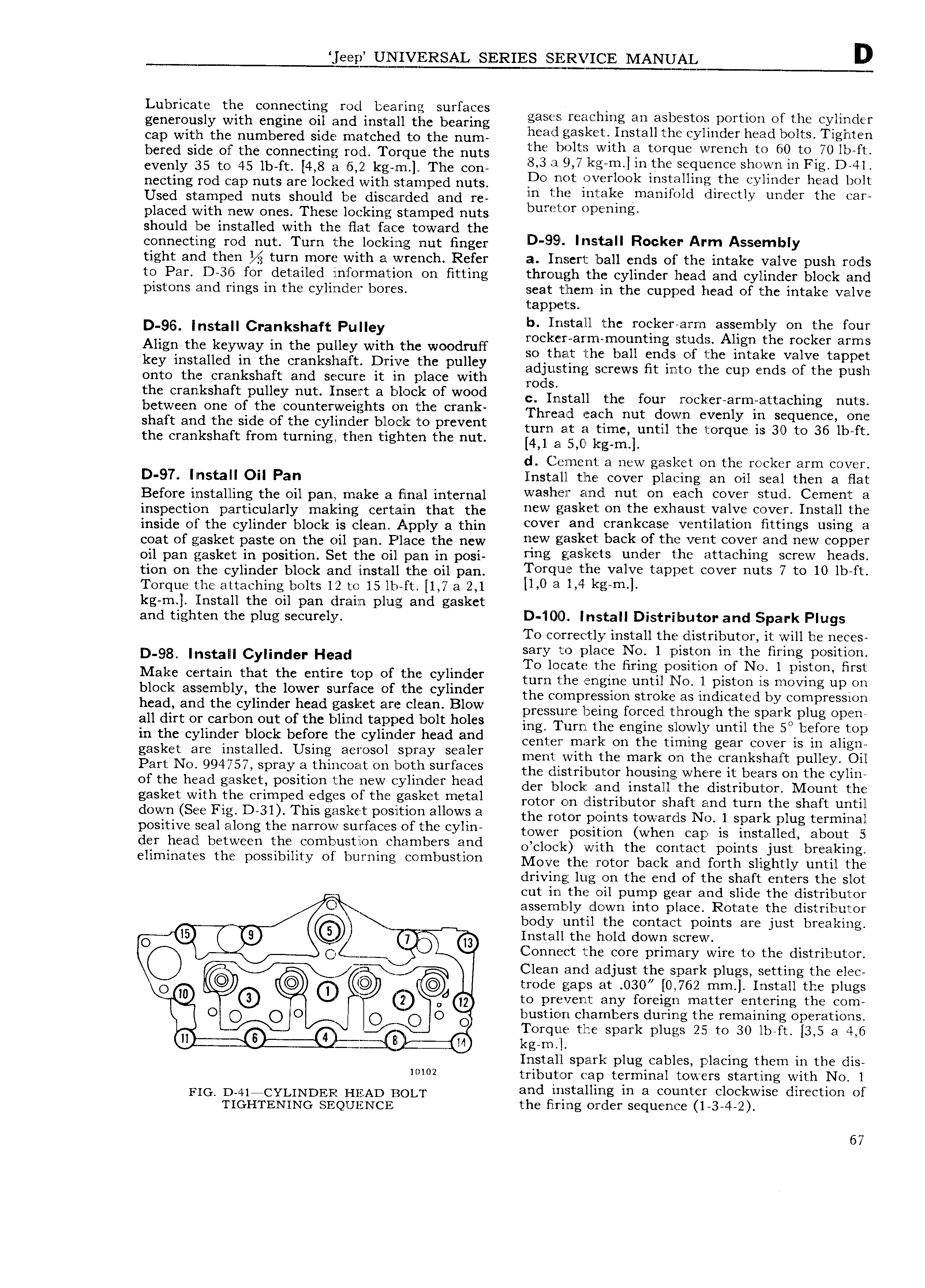
eep UNIVERSAL SERIES SERVICE MANUAL D Lubricate the connecting rod bearing surfaces generously with engine on and instan the bearing gases reaching an asbestos portion ofthe cylinder Cap with tho numbered Side matched to the num head gasket Install the cylinder head bolts T1gKll H bcfcd side of the connecting foot Torque the nuts the bolts with a torque wrench to 60 to 70 lb ft evenly 35 tO 45 lb ft 4 8 3 15 2 kg m The CO 83 ii 9 7 kE YU l 1U th iS QL1 HC shoxivn in F1g D 41 looting rod Cap nuts me iockcd with Stamped nutsl po not overlook installirigthe cylinder head bolt Used Stampod nuts should be discarded and r in the intake manifold directly under the car placed with new ones These locking stamped nuts b l l p l g should be installed with the flat face toward the connecting rod nut Turn the locking nut finger D 99 IM fall Rocker Arm A mblY tight and then turn more with a wrench Refer a Insert ball ends of the intake valve push rods to Par D 36 for detailed inzformation on fitting through the cylinder head and cylinder block and pistons and rings in the cylinder bores seat tlhern in the cupped head of the intake valve tappets D 96 Install Crankshaft Pulley b Install the roeker arm assembly on the four rocker arm mounting studs Align the rocker arms Allgll me kcyllvay ln the pulley Wltlil thi Woodruff so that the ball ends of the intake valve tappet key 1 St alkd m the f kShak Dm he pulkv adjusting screws at into nun nun ends nr nin push onto the crankshaft and secure it in place with rods the Cmkskeft pulky nut I k 3 k 1 k Of Wood C l1nrntn11 tnn nun rocker arm attaching nuts between one of the counterweights on the crank i hmoo mach out down ovcniy in Sequence ono shaft and the side of the cylinder block to prevent tum at 2 time umn tho torque is ao to 36 ib i t the crankshaft from turning then tighten the nut 4 el syo kg m1i d Cernent a new gasket on the rocker arm cover D 97 l r1staIIOlI Pan Install the cover pl a ing an oil seal then a flat Before instaiiing the oii panty make a Einlatl intetnai washer and nut on each cover stud Cement a inspection oai tiouiatiy malizirlg Ceietiaiin that the new gask et on the exhaust lvalve cover Install the inside oi the eyiindet block is oieann Akpply a thin cover and crankcase ventilation fittings using a coat of gasket paste on the oii t an piaoe the new new gasket back of the vent cover and new copper oii pan gasket in position Set tile oi patn in posi ring gaskets under the attaching screw heads tion on the cylinder block and install the oil pan TOY ll 1 UN valve 3P P t 0V Y nuts 7 to 10 lb ft Torque the attaching bolts 12 to 15 lb ft 1 7 a 2 1 ll 0 9 1 4 k 1 l kg m Install the oil pan drain plug and gasket and tighten the plug securely D 1040 Install Distributor and Spark Plugs To correctly install the distributor it will be neces D o8 Insta Cylinder Head slary to place No 1 piston in the firing positione o locate the Hrmg position of No l piston first Make Ccllitam that thc clltllic lll Oli ljhlil cylllldcli turn the engine until No l piston is moving up on Hloak aszclglbllyi llfllg logelidsilllliilri flf l gl aiylgl the compression stroke as indicated by compression Sad all sbcy lll ell f cl fs ict E l edi It h 1 pressure being foreed through the spark plug open Fl lll Olkcal Oll out O l lllf allpc 0 O cs mg 1 urn the engine slowly until the 5D before top lll ths cyllllflcll block bclllllc the Cylllldcr head and center mark on the timing gear cover is in align gasket ale lilslallell Uslllg 3 l OSOl Splay Sealer ment with the mark on the crankshaft pulley Oil Pall N 994 75 spmy a tlllll O lt Oll l Olll Surfaces the distributor housing where it bears on the cylin Of the had gasket S1 the new yk kf had nnn block and install r nn nutnnu nn Mount un gasket Wltll the Cllmpecl dg S tllli gasket metal rotor on distributor shaft and turn the shaft until dOVYll See Fl D 3l Tllls gllskel pOsltlOll allows 3 the rotor points towards No 1 spark plug terminal positive seal along the narrow surfaces of the cylm towel position Whoo ego is installed about 5 dsl lleadl b tW ll h COmb llstlOll Clllllllbsls and o clock with the contact points just breaking ellmmates the lmsslblllty Ol bllmlllg Cgmbusllon Move the rotor back and forth slightly until the driving lug on the end of the shaft enters the slot cut in the oil pump gear and slide the distributor C assembly down into place Rotate the distributor body until the contact points are just breaking O 7 Install the hold down screw C 4 D Connect the core primary wire to the distributor Q g3 Ij Clean and adjust tn spark plugs setting the elec 40 trode gaps at 030 0 762 mm Install the plugs O k Q3 Q to prevent any foreign matter entering the com O O O O O C O O bustion chambers during the remaining operations l x Torque the spark plugs 25 to 30 lb ft 3 5 a 4 6 W l l b Q kg m Install spark plug cables placing them in the dis IOW tributor cap terminal towers starting with No l FIG D 4iiCYLiNDER HEAD BOLT and installing in a counter cloclgwise direction of TIGHTENING SEQUENCE the firing order sequence 1 3 4 2 67