Ford Parts Wiki | GM Parts Wiki
Home | Search | Browse
Prev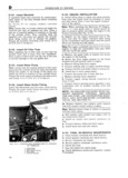
 Next
Next
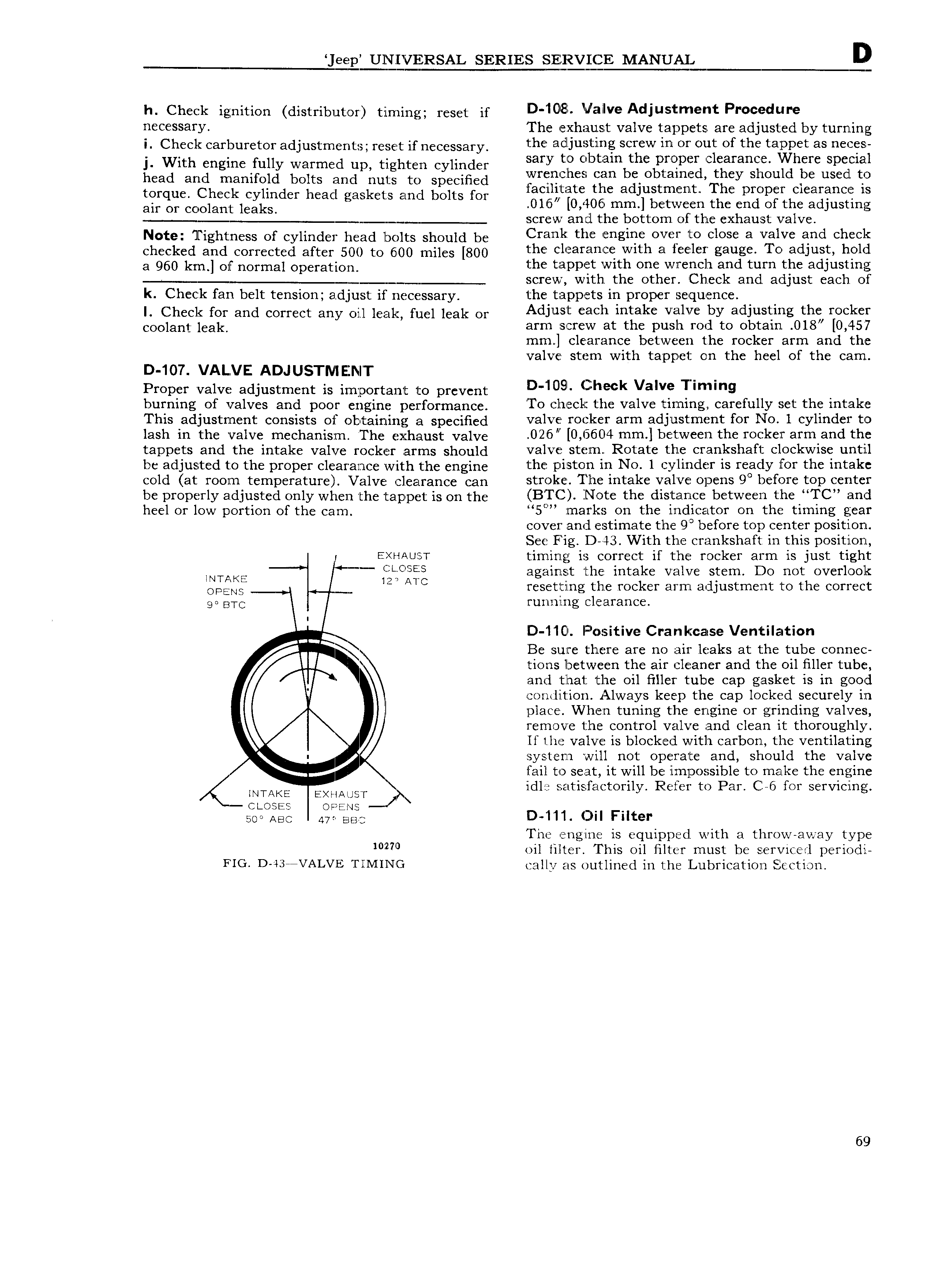
eep UNIVERSAL SERIES SERVICE MANUAL D h Cheek ignition distributor timing reset if D 10 8l Valve A i f Pr dur C SSHry The exhaust valve tappets are adjusted by turning i Check carburetor adjustments reset if necessary the il i 5 s Screw in OY Out Of the taippct as S j With engine fully warmed np tigh ten cylinder my VO b th p p 1 Wh Sp head and manifold bolts and nu1 s to specified iivrgxichcs can b b d they Sh ld e used to tOrquC Check Cylinder head gaskets and bolts for tacilktate the adjustment The proper clearance is ai Or Coolant leaks 016 0 406 mm between the end of the adjusting j T screw and the bottom of the exhaust valve Note Tightness of cylinder head bolts should be Creek tim Bngigc OV to close a valve and Check Checked and Corrected after 500 to 6 00 miles 800 the clearance with a feeler gauge To adjust hold 3 950 km gf normal Oparatioa the tappet with one wrench and turn the adjusting L screw with the other Check and adjust each of k Check fan belt tension adjust if necessary the tappets in proper sequence i cheek ree and correct any on leak fuel leak or Adjust h i k MVC by di Sti g the r k r Coojant j ak arm serew at the push rod to obtain 0l8 0 457 mm clearance between the rocker arm and the valve stem with tappet on the heel of the cam D 107 VAL VE ADJUSTNIEZNT Proper valve adjustment is important to prevent D 10 g C h k Valve Tmimg burning of valves and poor engine performance To check the valve timing carefully set the intake This adjustment consists of obtaining a specified V3lV Y0 k arm adi Stm for NO 1 Cyhndcli UD lash in the valve mechanism The exhaust valve 026 0 6604 mm b t W thi r rkc r arm and the tappets and the intake valve rockeer armg should valve stern Rotate the crankshaft clockwise untill be adjusted to the proper clearance with the engine the piston in No 1 cylinder is ready for the intake cold at room temperature Valve e rranc can stroke The intake valve opens 9 before top center be properly adjusted only when the rapper is on the BTC Note the distance between the TC and heel or low portion of the cam 5 marks on the indicator on the timing gear cover and estimate the 9 before top center position See Fig D 43 With the crankshaft in this position E HAusT timinggg is correct if the rocker arm is just tight WTAKE against the intake valve stem Do not overloolk Opgm resettrng the rocker arm adjustment to the correct ae B C running clearance I D 1 1Cl F sitive Crankcalse Ventilation Q Be sure there are no air leaks at the tube connecz tions between the air cleaner and the oil filler tube and that the oil filler tube cap gasket is in good eondltion Always keep the cap locked securely in I place When tuning the engine or grinding valves remove the control valve and clean it thoroughly If the valve is blocked with carbon the ventilating system will not operate and should the valve fail to seat it will be impossible to make the engine INTAKE EXHAUST idle satisfactorily Refer to Par C 6 for servicing ctoses opens 500 Agg Aye BB The engine is equipped with a throw away type oil lilter This oil filter must be serviced periodi FIG D 43 VALVE TIMING cally as outlined in the Lubrication Section 69