Ford Parts Wiki | GM Parts Wiki
Home | Search | Browse
Prev
 Next
Next
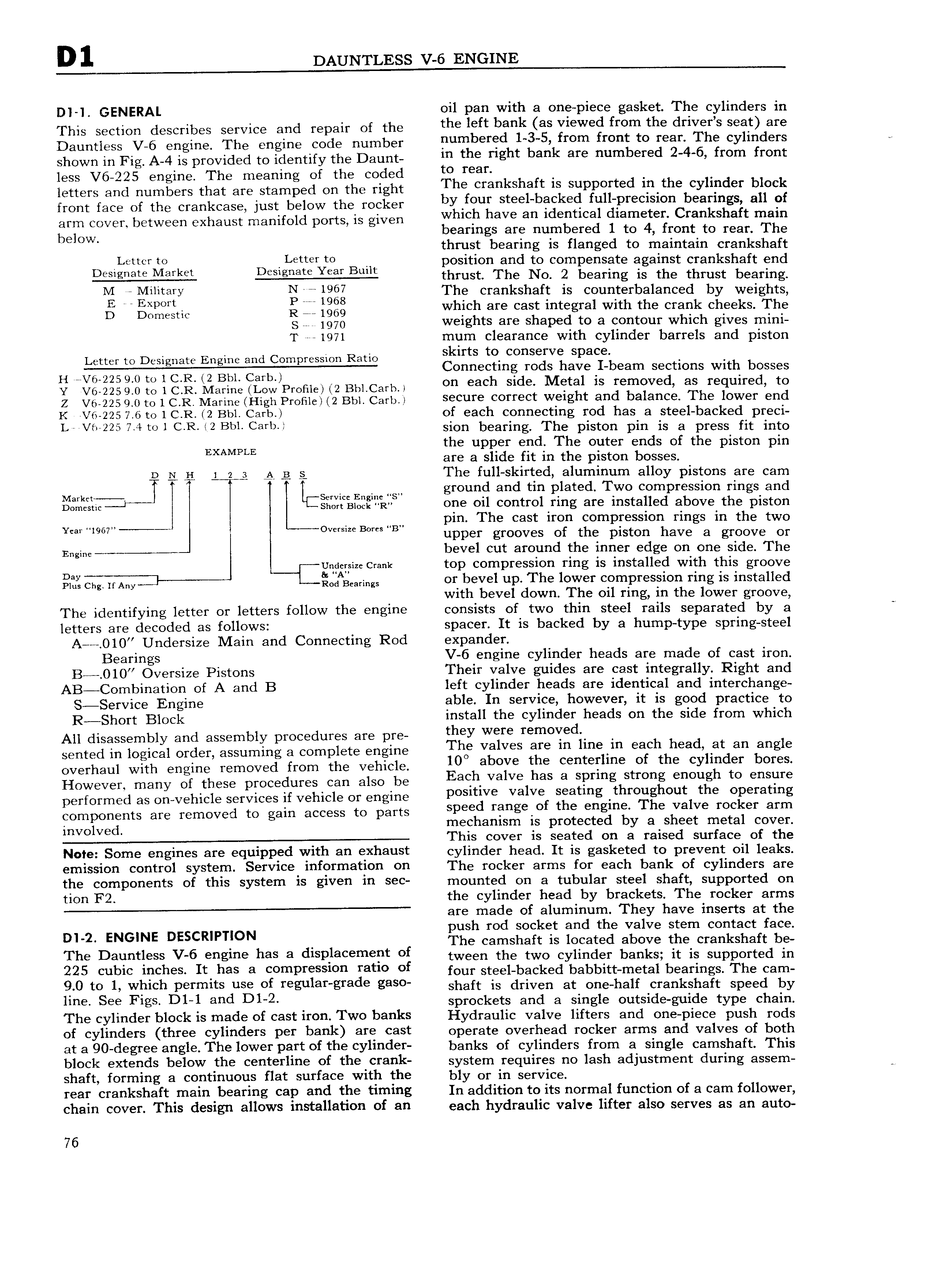
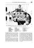
D1 DAUNTLESS V 6 ENGINE Dl 1 GENERAL oil pan with a one piece gasket The cylinders in This section describes service and repair of the the left bahk as Viewed from the dYiV i i 930 3Y Daumjgss V 6 Qngima The Engine Code number numbered 1 3 5 from front to rear The cylinders shown iii Fig A 4 is provided to ideiiniy the Daunt m the right b i are mi d 2 4 6 fmm from less V6 225 engine The meaning of the coded le leelh letters and numbers that are stamped on the right The Crankshaft ls Supported lll lhe eYlllldeY block front face of the crankcase just below the rocker hY lO ll Sleehbeekecl lllll Pleelsl ll beallhgsv all ef arm COVER between exhaust manifold ports is given which have an identical diameter Crankshaft main below bearings are numbered 1 to 4 front to rear The thrust bearing is flanged to maintain crankshaft L r 10 i t r t0 position and to compensate against crankshaft end thrust The No 2 bearing is the thrust bearing M r Miiitary Nin i967 The crankshaft is counterbalanced by weights S 7 i gl iilggm ll li iggg which are cast integral with the crank cheeks The S 1970 weights are shaped to a contour which gives mini T 1971 mum clearance with cylinder barrels and piston skirts to conserve space H OOIi S g 3 EHTQEF Zrgbcsmpiessmn Ram Connecting rods have UI beam sections with bosses Y V6 2259i0 id ic R Marine LoWPren1e 2 Bn1 carn Oh each Sl le Metal is lemavadi as required 0 Z V6 225 9 0 to l C R Marine High Profile 2 Bbl Carb S Ci ii correct weight and balance The l0W I 6Hd K V6 225 7 6 to 1C R 2 Bbl Carb of each connecting rod has a steel backed preci i i Vi i22 7 mi C R l2 Bi i Caib i sion bearing The piston pin is a press fit into EXAMPLE the upper end The outer ends of the piston pin are a slide f1t in the piston bosses D 5 5 L 2 g A a s The full skirted aluminum alloy pistons are cam Mmm T l Y LESQMCC Engine S ground and tin plated Two compression rings and Domestic J sh iBi Ci R one oil control ring are installed above the piston H I I pin The cast iron compression rings in the two Y il l 6l S B B upper grooves of the piston have a groove or Engine bevel cut around the inner edge on one side The uiidersize crank top compression ring is installed with this groove gif 3 Any QdAB a g or bevel up The lower compression ring is installed with bevel down The oil ring in the lower groove The identifying letter or letters follow the engine consists of two thin steel rails separated by a letters are decoded as follows spacer It is backed by a hump type spring steel A O10 Undersize Main and Connecting Rod expander Bearings V 6 engine cylinder heads are made of cast iron B O10 Oversize Pistons Their valve guides are cast integrally Right and AB Combination of A and B left cylinder heads are identical and interchange S Service Engine able In service however it is good practice to R Short Block install the cylinder heads on the side from which All disassembly and assembly procedures are pre they were lem0Yed sented in logical order assuming a complete engine The valves ele lh llha ih each head at all ahgle overhaul with engine removed from the vehicle 10 above the eelltelilllle Ol the cylllldeli b l es However many of these procedures can also be E3Qii valve has 3 spring Strong enough to ensure performed as on vehicle services if vehicle or engine pesltlve Valve seetlllg llll llgll ut the Opelatlhg components are removed to gain access to parts Speed lellgeel the ellgllle The Valve locker elim involved mechanism is protected by a sheet metal cover This cover 1S seated on a raised surface of the Note Some engines are equipped with an exhaust cylinder head It is gasketed to prevent oil leaks emission control system Service information on The rocker arms for each bank of cylinders are the components of this system is given in sec mounted on a tubular steel shaft supported on tion F2 the cylinder head by brackets The rocker arms are made of aluminum They have inserts at the ush rod socket and the valve stem contact face Dl 2 ENGlNE DESCRIPUON The camshaft is located above the crankshaft be The D6 ti S V 6 Biigiiie has a diSP iaeemehi Of tween the two cylinder banks it is supported in 225 Cubic i Ch S It iiaS a Cempiessleh latle Ol four steel backed babbitt metal bearings The cam 9 0 to ii Which Permits use of iegulahglade gaS shaft is driven at one half crankshaft speed by ii 68 Figs Dlri and Dl 2 sprockets and a single outside guide type chain The cylinder block is made of cast iron Two banks Hydraulic valve lifters and one piece push rods of cylinders three cylinders per bank are cast operate overhead rocker arms and valves of both at a 90 degree angle The lower part of the cylinder banks of cylinders from a single camshaft This block extends below the centerline of the crank system requires no lash adjustment during assem shaft forming a continuous flat surface with the bly or in service rear crankshaft main bearing cap and the timing In addition to its normal function of a cam follower chain cover This design allows installation of an each hydraulic valve lifter also serves as an auto 76