Ford Parts Wiki | GM Parts Wiki
Home | Search | Browse
Prev
 Next
Next
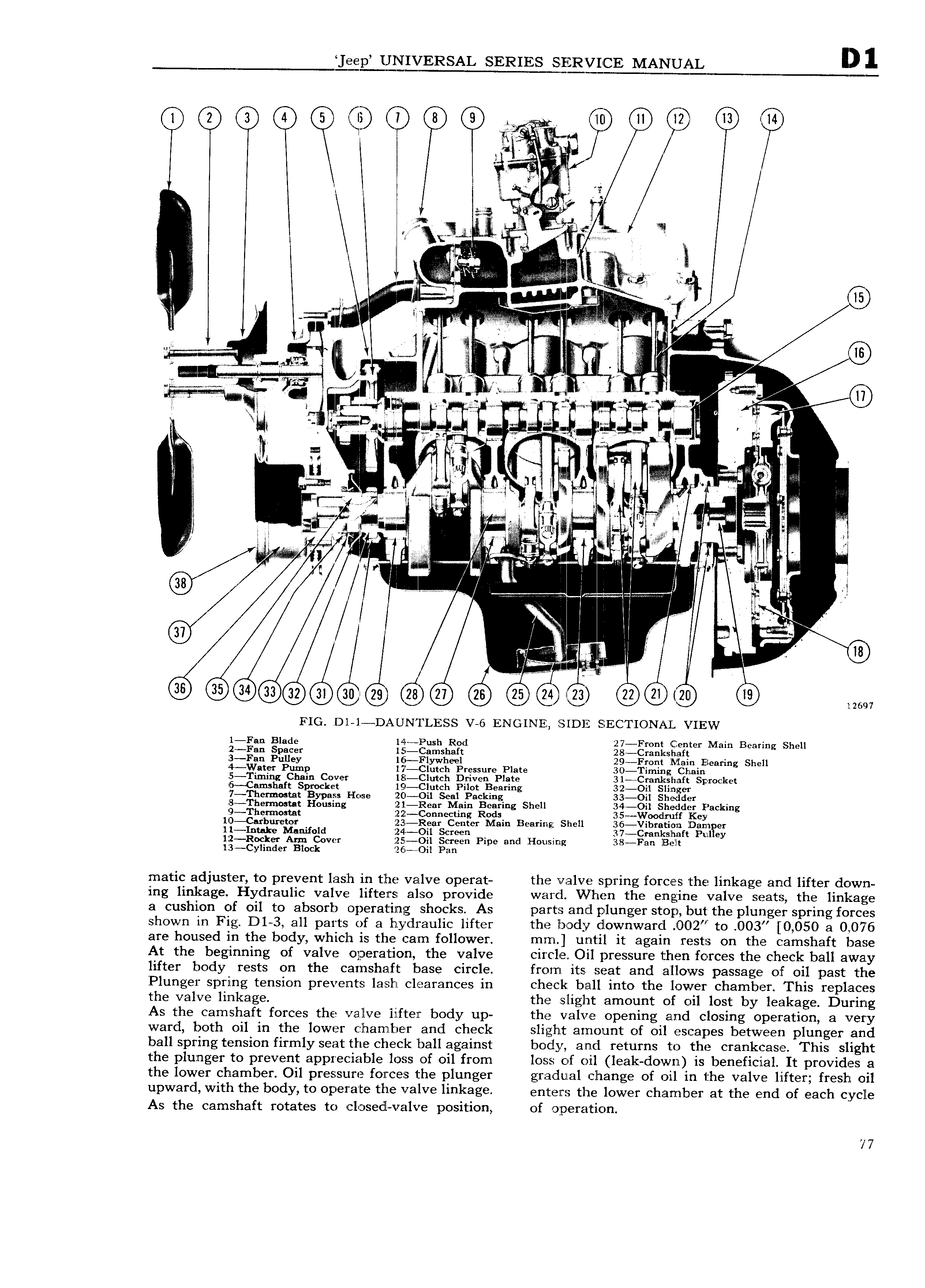
lien IELTEVERSAL SERIES MANUAL 1 4 O C0 0 6 ie t 0 60 w v nal F ii 7 is y fi i JV 4 I s gi W 3 a T SS4 se i J x I i il i I fi is v V Y 2 J M WSME 7 1 7 Q 5 1 M 4 wg i 2 tx i m P 0 V7 l i ii W WJ P if K V EI 0 y l i M 4 5 li QAQ V in sv vi i W I i C A T gl V 7 g if Nm m 2 or W gl Y Yi X I l l i r i Z G ifl i if li all i if my r Q Q li 5 y 4 Zi 9 I 2 li W a J l 7 A S V VA V me rl 5 is I 4 5 Gy 291 2 Q Q6 9 2 90 W FIG Dl l DAUNTLESS V 6 ENGINE SIDE SECTIONAL VIEW l Fan Blade l4l Push Rod 27 Front Center Main Bearing Shell 12 Fan Spacer l5 Camshaft 28 Crankshnft 13 Fan Pulley 16 Flywheel 29 Front Main Bearing Shell 4 Water Pump l7 Clutch Pressure Plate 30 I iming Chain 5 Timing Chain Cover lEI Clutch Driven Plate 31 Cmnkshaft Sprocket 45 CamshaIt Sprocket l9 Clutch Pilot Bearing 32 Oil Sliznger 7 Tberm0stat Bypass Hose Z0 Oil Seal Packing 33 Oil Shedder lB Thenu0stat Housing fZl Rear Main Bearing Shell 34 Oil Shedder Packing 9 1 hermostnt 1Z2 Connecting Rods 35 Wooclruff Key l0 Carburetor iZ3i Rear Center Main Bearing Shell 36 Vibrat ii n Dam er 1l Intake Manifold 24 Oil Screen 37 Crnnkshaft Pulley ll o rerA C ovcrr ggxsen Pipe and Housing 38 Fan lBeIlt matic adjuster to prevent lash in the valve operat the valve spring forces the linkage and lifter down ing linkage Hydraulic valve lifters also provide ward When the engine valve seats the linkage a cushion of oil to absorb operating shocks As parts and plunger stop but the plunger spring forces shown in Fig Dl 3 all parts of a hydraulic lifter the lmody downward JD02 to 003 0 050 a 0 076 are housed in the body which is the cam follower mm until it again rests on the camshaft base At the beginning of valve operation the valve circle Oil pressure then forces the check ball away lifter body rests on the camshaft base circle from its seat and aiiows passage of oil past the Plunger spring tension prevents lash clearances in check ball into the lower chamber This replaces the valve linkage the slight amount of oil lost by leakage During As the camshaft forces the valve lifter body up the valve opening and closing operation a very ward both oil in the lower crhamiber and check slight amount of oil escapes between plunger and ball spring tension firmly seat the check ball against body and returns to the crankcase This slight the plunger to prevent appreciable loss of oil from loss of oil leak down is beneficial It provides a the lower chamber Oil pressure forces 1 he plunger gradual change of oil in the valve lifter fresh oil upward with the body to Op l a E the valve llI1k3g enters the lower h anib er at the end of each cycle As the camshaft rotates to r l sedl valve position of operation 77