Ford Parts Wiki | GM Parts Wiki
Home | Search | Browse | Marketplace | Messages | FAQ | Guest
Prev
 Next
Next
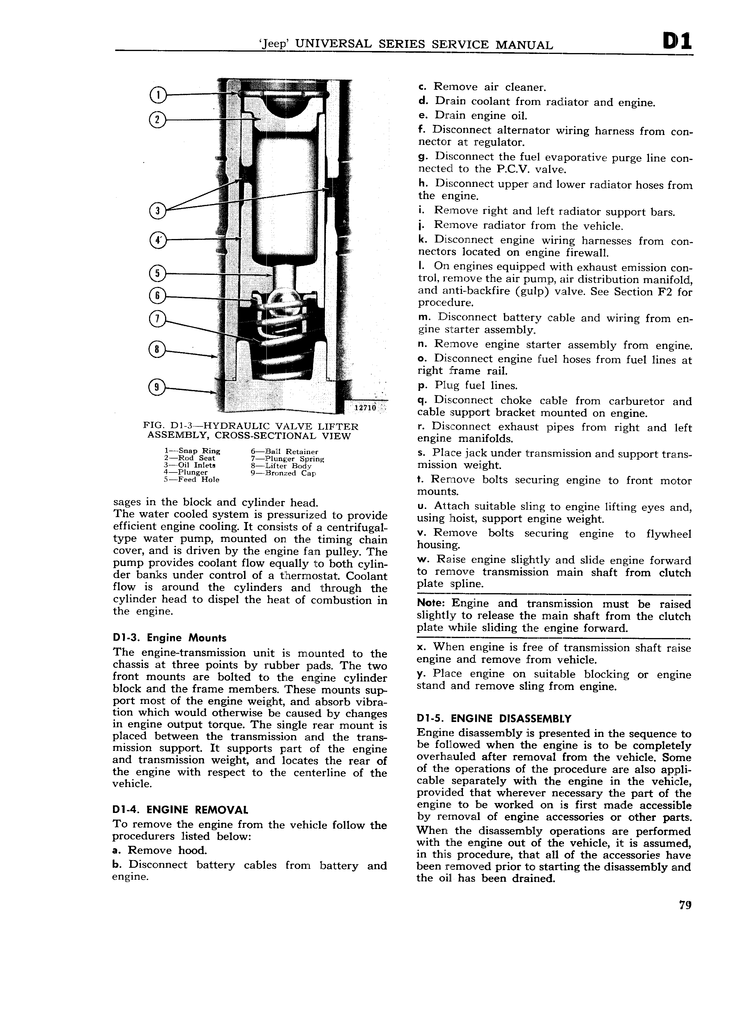
eep UNIVERSAL SERIES SERVICE MANUAL Q i l i Q c Remove air cleaner Cl Q d Drain coolant from radiator and engine C i I e Drain engine oil 6 QIQZQN I I Z i 2 f Disconnect alternator wiring harness from con t I nector at regulator Q Q g Disconnect the fuel evaporative purge line con F Z 5 nectecil to the P C V valve h Disconnect upper and lower radiator hoses from Ki V Q if the engine C i Remove right and left radiator support bars Zigi iig 1 I i Remove radiator from the vehicle Cf i l Dl StCOl7tI1 Ct engine wiring harnesses frgm cgrl if nectcnrs located on engine firewall I by Y V V I I On engines equipped with exhaust emission con Q trol remove the air mump air distribution manifold I I y Y Q gi T M and anti backfire gulp valve See Section F2 for Q V procedure C ll m Disconnect battery cable and wiring from en gine starter assembly K A g Remove engine starter assembly from engine if M l 0 Disconnect engine fuel hoses from fuel lines at II ih V I right frame rail QI I J liili p Plug fuel lines V T 3 q D i scon nect choke cable from carburetor and 4 12710 cable support bracket mounted on engine FIG D1 3 HYDRAUL1 VALVE 1 nr rER r Disconnect exhaust pipes from right and left ASSEMBLY CROSS SEICTIONAL VIEW gngirjg nq ay tifOldS 1 S p Ring 6 1B iH Retainer s Place jack under transmission and support trans 2 Rod Seat 7 lPlung er Spring 2 1 Init ts 8 gcarta Body H11SS1 0 Wfilghf szrfiiigiiioie 9 Bmm d can 1 Remove bolts securing engine to front motor mounts S8 in the block and Cyiirldlx h d u Attach suitable sling to engine lifting eyes and Th W3lf I C OI d system IS pI SSLlI ZlZ4Bd ICO pI OV1d using hoist support engine efficient engine cooling It consists of acentrifugal v Rgmove bolts securing engine to flywheel type water pump mounted on the timing chain housing cover and is driven by the engine fan pulley The R 1 ht d 1 d f A 1 pump provides coolant flow equally to both cylin Else engine S lg y an S I gi anime Ol Tir der banks under control of a thermostat Coolant q 5 rlEO ransmlsslcm mam S A mm C u C I flow is around the cylinders and through the i ES Yli d h 6d to di P l th h 3l Of 0mb Sti0 in Note Engine and transmission must be raised h gm slightly to release the main shaft from the clutch plate while sliding the engine forward D 3 Engine Mounts x Wh en ine is fQ transmi n shaft vg The engine transmission unit is mounted to the eilgim andgemove 1 n vehicle C chassis at three points by rubber pads The two P1 p p t l bl kin U hp front mounts are bolted to the engine cylinder yi dam jengme On iulfd Q ec lg or E g L block and the frame members These mounts sup S an lam remove S mg mm ngme port most of the engine weight and absorb vibra tion which would otherwise be caused by changes D 5 ENGINE DISASSEMBIIY in engine output torque The single rear mount is E d A mb p ted in th u nw to placed between the transmission and the trans bn uH lsgsseh nytlls PISSES is to I Sggme leta mission support It supports part of the engine e EQOENS X 6 le lgfrgm th Vehiclepsomx and transmission weight and locates the rear of Ogilixflu E cr regngvd d r 6 I alsc a Hf the engine with respect to the centerline of the 0 Opera Ions O le pmce u B 8 eh tglgl vehicle cable separately with the engine IH t e ve it e provided that wherever necessary the part of the Itl kd f t d bl 4I REMQVM i g Z i I3I r Z Z ZZ IZ Li L i i i1 To regmzve tile engine fr m the Vehicle follow the When the disassembly operations are performed proce mers lsted bel w with the engine out of the vehicle it is assumed Remvve h00d in this procedure that all of the accessories have b Disconnect battery cables from battery and been removed prior to starting the disassembly and engine the oil has been drained 79