Ford Parts Wiki | GM Parts Wiki
Home | Search | Browse | Marketplace | Messages | FAQ | Guest
Prev
 Next
Next
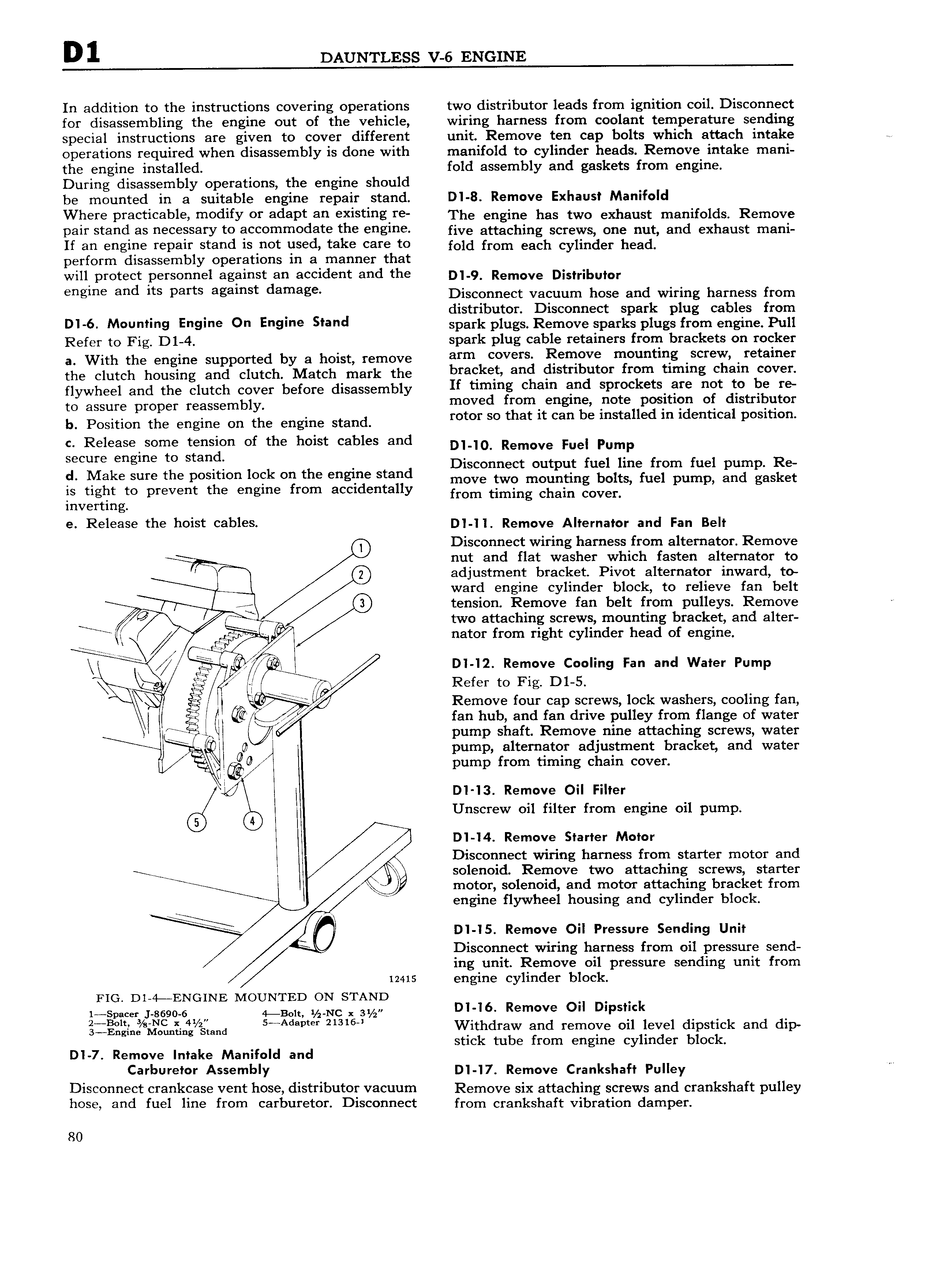
D1 DAUNTLESS V 6 ENGINE In addition to the instructions covering operations two distributor leads from ignition coil Disconnect for disassembling the engine out of the vehicle wiring harness from coolant temperature sending special instructions are given to cover different unit Remove ten cap bolts which attach intake operations required when disassembly is done with manifold to cylinder heads Remove intake mani the engine installed fold assembly and gaskets from engine During disassembly operations the engine should be mounted in a suitable engine repair stand Dl 8 Remove Exhaust Manifold Where PYeeti eble Yn0difY OT adept an existing I e The engine has two exhaust manifolds Remove p3lI stand HS HECCSSHYY to 3CCOIlHHl Od3t th Englne five attaching screws One nut and exhaust rnani If HH HglI I I p8lI stand is not used take Calle to fron each cylinder h ad perform disassembly operations in a manner that will protect personnel against an accident and the p 9 Remove Dmrgburor engme and its parts agamst damage Disconnect vacuum hose and wiring harness from distributor Disconnect spark plug cables from Dl 6 M Un ln9 En9lne On En9 ne Sland spark plugs Remove sparks plugs from engine Pull Refer to Fig D1 4 spark plug cable retainers from brackets on rocker a With the engine supported by a hoist remove arm eevells Ren Ve meuntieg seTeW retainer the oluroh housing and clutche Match mark the bracket and distributor from timing chain cover flywheel and the clutch cover before disassembly If Ummg chem and Spreckets are net to be Ye ro assure proper reassembly moved from engine lnote position of distributor bi Position the engine en the engine Stand rotor so that it can be installed in identical position c Release some tension of the hoist cables and D o Remove Fee Pump secure engine to stand cl Make sure the position lock on the engine stand Dlscollllllcl Olltplll llllll lllle llom llllll pump Re move two mounting bolts fuel pump and gasket is tight to prevent the engine from accidentally from timing ehein eevee inverting e Release the heist cables Dl ll Remove Alternator and Fan Belt Disconnect wiring harness from alternator Remove nut and flat washer which fasten alternator to adjustment bracket Pivot alternator inward to ward engine cylinder block to relieve fan belt tension Remove fan belt from pulleys Remove Q I ee two atgaching lslcrevtis gioulutinig I racket and alter tlr nator rom rig t cy in er ea 0 engine L Dl l2 Remove Cooling Fan and Water Pump l Refer to Fig D1 S Remove four cap screws lock washers cooling fan r fan hub and fan drive pulley from flange of water if 1 1 pump shaft Remove nine attaching screws water O O pump alternator adjustment bracket and water F g pump from timing chain cover 1 l b D1 13 Remove Oil Filter Unscrew oil filter from engine oil pump D1 I4 Remove Starter Motor Disconnect wiring harness from starter motor and l solenoid Remove two attaching screws starter g motor solenoid and motor attaching bracket from R engine flywheel housing and cylinder block D1 I5 Remove Oil Pressure Sending Unit Disconnect wiring harness from oil pressure send ing unit Remove oil pressure sending unit from 12415 engine cylinder block FIG Dl 4 ENGINE MOUNTED ON STAND eeeee yJ ee9o 64x e here Nh1 e DI I6 Remove Oil Dnpstick l s Engiaslilaaunlfing gtgnd M lvm 2 3 l Wlthdfaw and remove oil level dipstick and dip stick tube from engine cylinder block Dl 7 Remove Intake Manifold and C8l l Ufel0t A SemblY Dl I7 Remove Crankshaft Pulley Disconnect cfankcase vent hose distributor Vacuum Remove six attaching screws and crankshaft pulley hose and fuel line from carburetor Disconnect from crankshaft vibration damper 80