Ford Parts Wiki | GM Parts Wiki
Home | Search | Browse | Marketplace | Messages | FAQ | Guest
Prev
 Next
Next
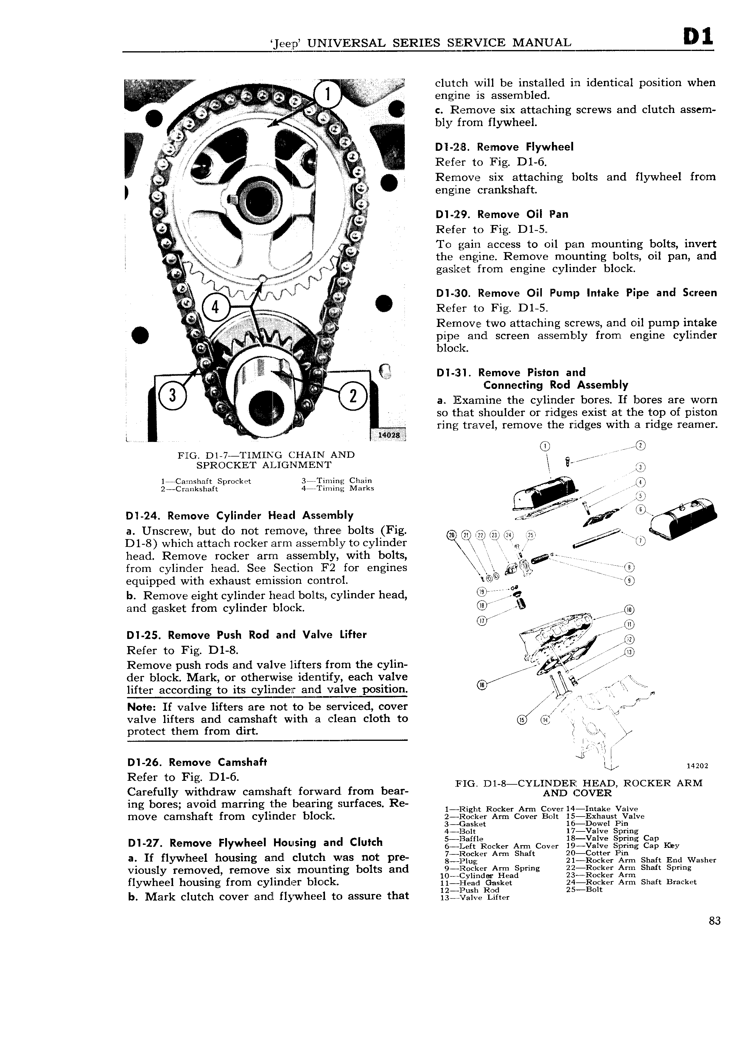
eejp UNIVERSAL SERIES SlE 3RVllCE MANUAL 1 g 1 clutch will be installed in identical position when iti iiii i w e l E iE iv i ensnie is assembled i i t l c Remove six attaching screws and clutch assem J t il ii bly from flywheel J 4 it i x l z Dl 1218 Resmove Flywheel fj 3 4 qw Refer to Fig D1 6 i t K i C in Remove Six attaching bolts and flywheel from l E iiiiiliiiiiiiiii E 9Ug l I 1 crankshaft W E Q D1 1129 Remove Oil Pan V gi Refer to Fig Dl 5 g jx To gain access to oil pan mounting bolts invert E Q jr the engine Remove mounting bolts oil pan and v f i gasket from engine cylinder block z k v gang rj s rvfixsefiw I Dl J30 Remove Oil Pump Intake Pipe and Screen L a 4 E Refer to Fig D1 5 V Remove two attaching screws and oil pump intake Ae y 2 al V pipe alldl screen assembly from engine cylinder S r blor l T s V 3 y r Dl 231 Remove Piston and F7 Z d Assembl gg onnectmg Ro y 6 3 2 a lliixamine the cylinder bores If bores are worn jy 2 3 l so that shoulder or ridges exist at the top of piston i ring travel remove the ridges with a ridge reamer L 1402ag z FllG Dl 7 TIMING CHAIN AND fr O SPROCKET ALIGNMENT l 1 Ca mshaft Sprocket 3 Timing Chain M V O 2 Cr 1nkshaft 4 I iming Marks 24 J Dl 24 Remove Cylinder Heacl Assembly g a Unscrew but do not remove three bolts Fig QQ QE QD 5 i D1 8 which attach rocker arm assembly to cylinder J6 r D head Remove rocker arm assembly with bolts gg gg from cylinder head See Section F2 for engines r equipped with exhaust emission control Q L if b Remove eight cylinder head bolts cylinder head i and gasket from cylinder block CU Hf I i i to 4 V J Dl 25 Remove Push Rod and Valve Lifter rar z Refer to Fig D1 8 2 I QQ U r 1 r Remove push rods and valve lifters from the cyl1n ii 2 b 4 e der block Mark or otherwise identify each valve Y srl 5 H y lifter according to its cyliincler andlglve position W f f n Note If valve lifters are not to be serviced cover R Q L j E J 5i4 valve lifters and camshaft with a clean cloth to protect them from dirt Q I l 4 l Dl 26 Remove Camshaft B LL 14202 Refer to Fig D1 6 FIG D1 8 CYLINDER1 HEAD ROCKER ARM Carefully withdraw camshaft forward from bear AND COVER lng bores avold I nar lng beaflng surfaces Re 1 Right Rocker Arm Covezr 14 Intake Valve move camshaft from cylinder block j2 cLm Am cover Bolt g gx1m s Dva1v Sas et owe in 4 l3olt 17 Valve Spring Dl 27 Remove Flywheel Housing ancl Clutch jjj ffl i Cker Am Cow lgjgjljj QQQQE gig my at If flywheel housing and clutch was not pre gjjj lf A S Q f Pj m Shaft End Washer viously removed remove six mounting bolts and 9 liineker Arm Spring 22 R eker Ann Shaft Spring 10 r l ylmd r Head Z3 Rocker Arm flywheel housing from cylinder blo ck ii iereaa Gasket 2g 0 ker Am shan Bracket b Mark clutch cover and flywheel to assure that l YZl TlL Z t 2 t 83