Ford Parts Wiki | GM Parts Wiki
Home | Search | Browse | Marketplace | Messages | FAQ | Guest
Prev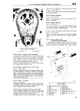
 Next
Next
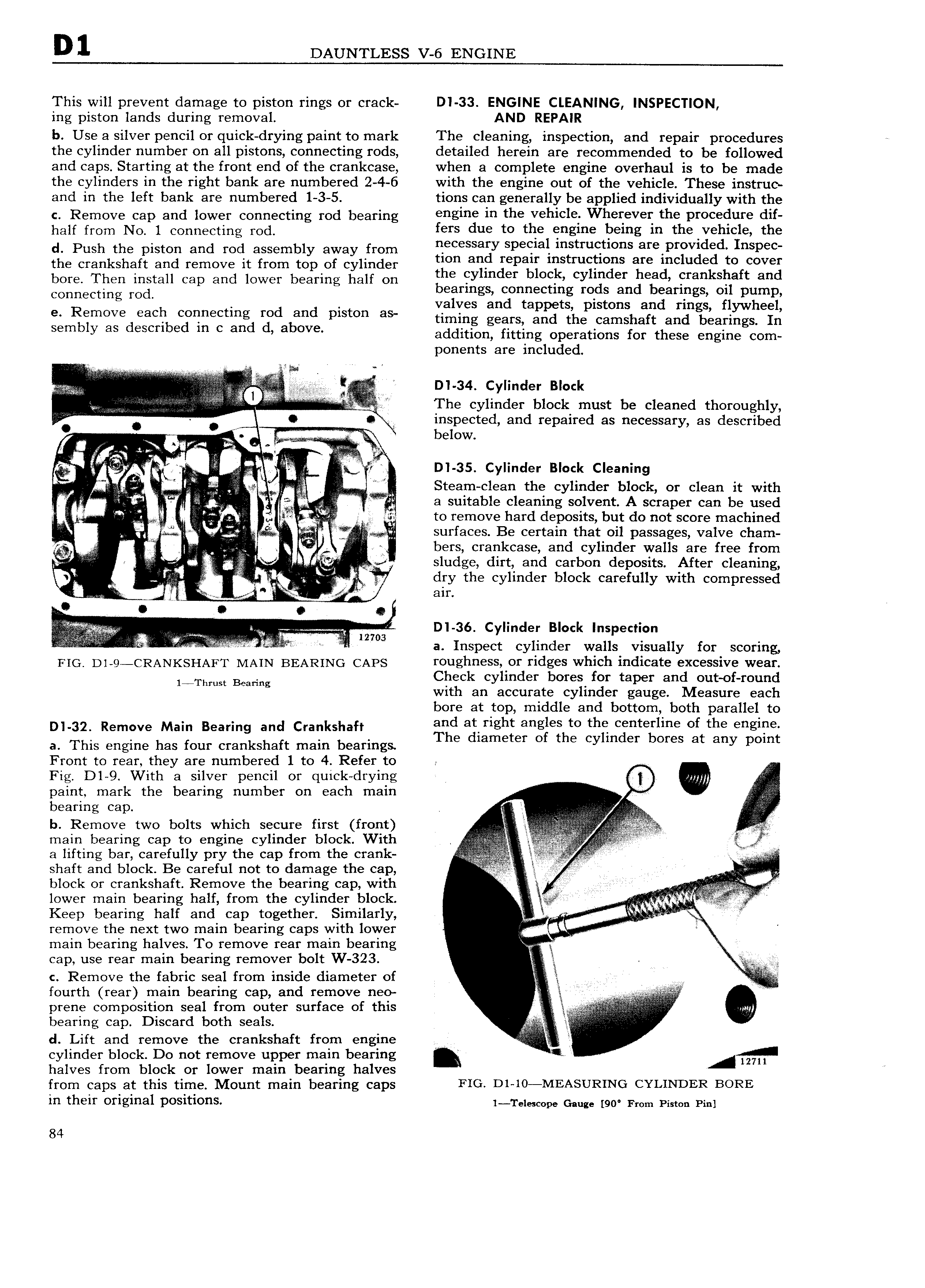
D1 DAUNTLESS V 6 ENGINE This will prevent damage to piston rings or crack DI 33 ENGINE CLEANING INSPECTION ing piston lands during removal AND REPAIR b Use a silver pencil or quick drying paint to mark The cleaning inspection and repair procedures e the cylinder number on all pistons connecting rods detailed herein are recommended to be followed and caps Starting at the front end of the crankcase when a complete engine overhaul is to be made the cylinders in the right bank are numbered 2 4 6 with the engine out of the vehicle These instruc and in the left bank are numbered 1 3 5 tions can generally be applied individually with the C Remove cap and lower Connecting rod bearing Hg1H in the vehicle Wherever the procedure half mm NI I Connecting md fers due to the engine being in the vehicle the d Push the piston and rod assembly away from eecessagy Speelal mstmetwns are pr Vlded InSpe the crankshaft and remove it from top of cylinder mm an bepee mstmellens eee Included be eever bore Then install cap and lower bearing half on bbe eylmder block cylinder beed eranksbaft and Connecting md bearings connecting rods and bearings oil pump e Remove each connecting rod and piston as Valves and tapp tS pistons and rmgS flywheel timing gears and the camshaft and bearings In eembb ee deeebbed lb e eee be ebbve addition fitting Operations rdr these edging adm ponents are included d w dd I 3 Y e A V e e V v ee e The Cylinder block must be cleaned thoroughly g o inspected and repaired as necessary as described V W i rg below 5 Ls V D1 35 Cylinder Block Cleaning Q V QQ VV if Steam clean the cylinder block or clean it with i f i I i A el a suitable cleaning solvent A scraper can be used V ei I to remove hard deposits but do not score machined I E V 2 surfaces Be certain that oil passages valve cham I li e e Y I bers crankcase and cylinder walls are free from V I h y sludge dirt and carbon deposits After cleaning Q za e e dry the cylinder block carefully with compressed V SM ee 1 V V ah e is bVf VV VV V VV ee VVV V I VVVV er r 3 Y b e e e h l I e e E I a Inspect cylinder walls visually for scoring I IG D Q QRANKSHAFT MAIN BEARING CAPS roughness or ridges which indicate excessive wear 1YThmst Beating Chick cylinder bores fgr taper an ilVIout of roung wit an accurate cy in er gauge easure eac bore at top middle and bottom both parallel to D 32 Remove Main Bearing and Crankshaft arnd at right angles to the centerline of the engine a This engine has four crankshaft main bearings he dlameter Of the cylmder bores at any pomt Front to rear they are numbered 1 to 4 Refer to e Fig D1 9 With a silver pencil or quick drying V 0 W paint mark the bearing number on each main beams eeb Ve V V V I V h Remcve me bolts which secure first hehe V V A r V VVe V r e g s main bearing cap to engine cylinder block With V 4 e I a lifting bar carefully pry the cap from the crank V J shaft and block Be careful not to damage the cap A block or crankshaft Remove the bearing cap with I lower main bearing half from the cylinder block see VV Keep bearing half and cap together Similarly ii L ii ii remove the next two main bearing caps with lower Q IK L main bearing halves To remove rear main bearing r cap use rear main bearing remover bolt W 323 gl e e w c Remove the fabric seal from inside diameter of it g W I I fourth rear main bearing cap and remove neo ie Q prene composition seal from outer surface of this iii l I i is bearing cap Discard both seals V IAI I d Lift and remove the crankshaft from engine I I cylinder block Do not remove upper main bearing halves from block or lower main bearing halves from caps at this time Mount main bearing caps FIG D1 10 MEASURING CYLINDER BORE in their Original pOSitiOnS 1 Telescope Gauge 90 From Piston Pin 84