Ford Parts Wiki | GM Parts Wiki
Home | Search | Browse | Marketplace | Messages | FAQ | Guest
Prev
 Next
Next
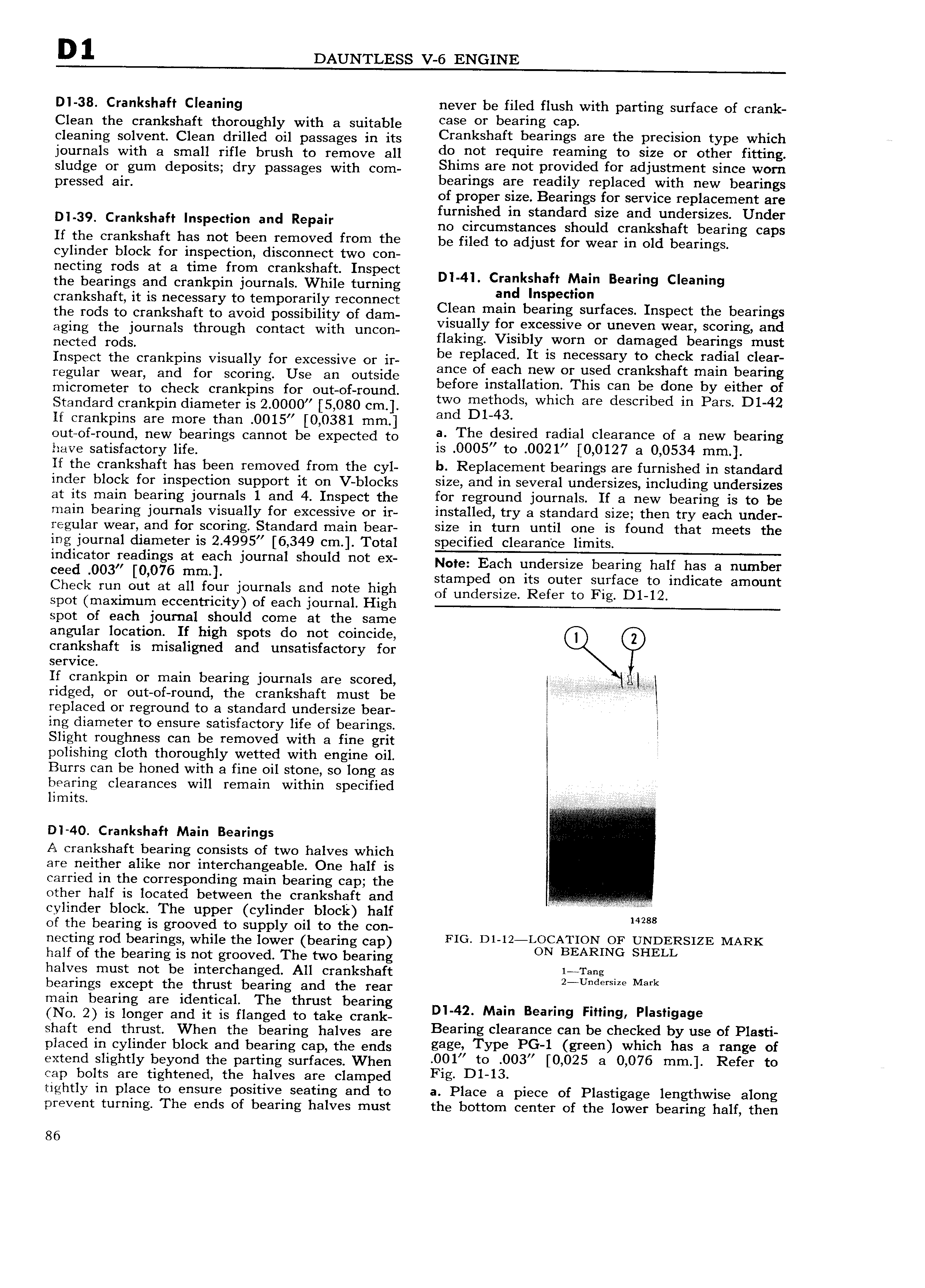
D 1 DAUNTLESS V 6 ENGINE Dl 38 Crankshaft Cleaning never be filed flush with parting surface of crank Clean the crankshaft thoroughly with a suitable eeee er heer hs e1 cleaning solvent Clean drilled oil passages in its Crankshaft neerrrrgs ere the Rreersren type which journals with a small rifle brush to remove all denier require reemmg to srze or ether rrtrrrrg sludge or gum deposits dry passages with Com Sh1IT1 8I not pfOY1d d for adjustment since worn pressed ain bearings are readily replaced with new bearings of proper size Bearings for service replacement are furnished in standard size and undersizes Under Dl 39 Crankshaft l Pe l n and Repn no circumstances should crankshaft bearing caps If the crankshaft has not been removed from the bg filed to adjust for wear in old bearing cylinder block for inspection disconnect two con nectin rods at a time from crankshaft Inspect the beirings and crankpin journals While turning Dl 4l Cragkihafl Tam Bearmg Cleamng crankshaft it is necessary to temporarily reconnect C1 en bnsllec mn f I t h b the rods to crankshaft to avoid possibility of dam aI 1m m eel Hlg Sur ac S nspec t S rarmgs aging the journals through contact with unoon Ken Y er eX ess e er uneven Weeh seenngr and nected rods aking Visiblyhworn or damaged bearings must Inspect the crankpins visually for excessive or ir be rep acedh It ls necessgry tokcgegk ralhal clear regular wear end for scoring Use an outside gnee ee eew er eee Cree S etn e n beenng efore installation This can be done by either of micrometer to check crankpins for out of round t th d h h d b d P D1 42 Standard crankpin diameter is 2 0000 5 080 cm W3 gi 4 s W lc ere esen 6 m ars If crankpins are more than 0015 0 0381 mm an out of round new bearings cannot be expected to e The geared reghel eleerehee ef e new heerrhe jmve Satisfactory mg is 0005 to 0021 0 0127 a 0 0534 mm If the crankshaft has been removed from the cyl b Replacement bearings are furnished in standard inder block for inspection support it on V blocks size and lll S V I 3l l1I 1d 1 SlZ S ll 1ClL1Cll g l 1IlCl I SlZ S at its main bearing journals 1 and 4 Inspect the for reground journals If a new bearing is to be main bearing journals visually for excessive or ir installed try a standard size then try each under regular wear and for scoring Standard main bear size in turn until one is found that meets the ing journal diameter is 2 4995 6 349 cm Total specified clearance limits indicator readings at each journal should not ex Note Each Lmdersize bearing half has 3 number ceed 003 076 mm l stamped on its outer surface to indicate amount Check run out at all four jOuI IlalS and note hlgh Of undcrsizer Refer tO Fig D1 12 spot maximum eccentricity of each journal High spot of each journal should come at the same angular location If high spots do not coincide crankshaft is misaligned and unsatisfactory for service If crankpin or main bearing journals are scored i ridged or out of round the crankshaft must be i U S replaced or reground to a standard undersize bear ing diameter to ensure satisfactory life of bearings Slight roughness can be removed with a fine grit V polishing cloth thoroughly wetted with engine oil Burrs can be honed with a fine oil stone so long as bearing clearances will remain within specified D I 40 Crankshaft Main Bearings A crankshaft bearing consists of two halves which are neither alike nor interchangeable One half is carried in the corresponding main bearing cap the other half is located between the crankshaft and cylinder block The upper cylinder block half 14288 of the bearing is grooved to supply oil to the con necting rod bearings while the lower bearing cap FIG Dr 12 LOCATION OF UNDERSIZE MARK half of the bearing is not grooved The two bearing ON BEARING SHELL halves must not be interchanged All crankshaft r re e bearings except the thrust bearing and the rear 2 U dmlZ Mark main bearing are identical The thrust bearing No 2 is longer ene n is rienged to nee erenie 4 Mem e r e F e e e e shaft end thrust When the bearing halves are Bearing eleererree een he cheeked by use of P1 placed in cylinder block and bearing een the ends gage Type PG 1 green whreh hes e range of extend slightly beyond the parting surfaces When 0O1 re 003 0 025 3 0 076 mm il Refer to cap bolts are tightened the halves are clamped Frg D1 13 tightly in place to ensure positive seating and to a Place a piece of Plastigage lengthwise along prevent turning The ends of bearing halves must the bottom center of the lower bearing half then 86