Ford Parts Wiki | GM Parts Wiki
Home | Search | Browse | Marketplace | Messages | FAQ | Guest
Prev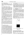
 Next
Next
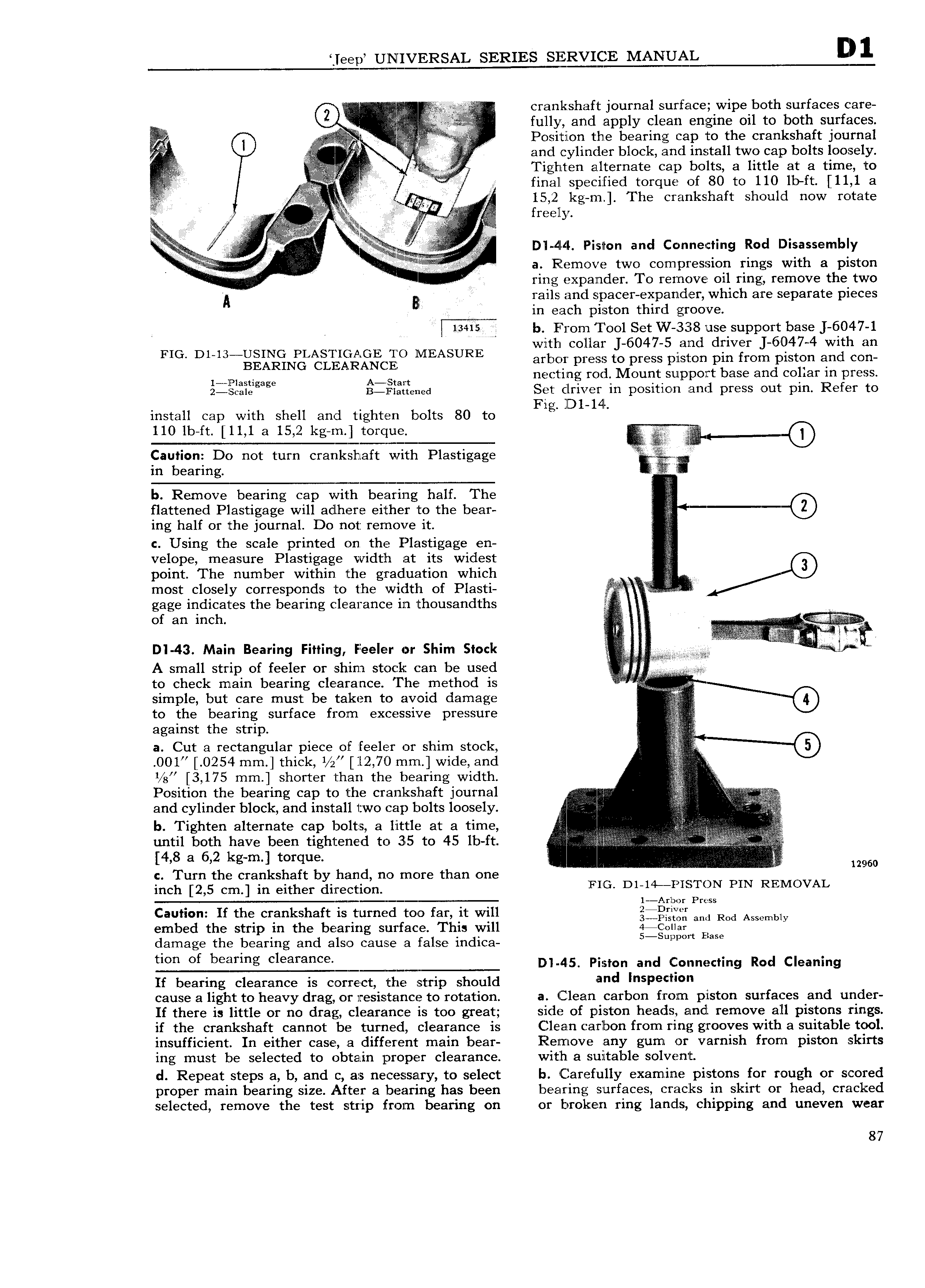
leep UNIVERSAL SERIES SIEERVIQE MANUAL Q V crankshaft journal surface wipe both surfaces care l t full V and apply clean engine oil to both surfaces 1 2 i 2 2 A i ii i POSIUOH the bearing cap to the crankshaft journal i and cylinder block and install two cap bolts loosely ll if Tighten alternate cap bolts a little at a time to final specified torque of 80 to 110 lb ft 11 1 a E E EE A wfkiif NQ VV g5 2 kg m The crankshaft should now rotate Y tti EEEE Ei E E t iiiii nn M l ff Ailn ilil V D1 4I 4 Piston and Connecting Rod Disassembly I i 5 V V z a pggcmove two compression rings With 8 pist ring expander To remove oil ring remove the two VA E rails and spacer expander which are separate pieces in each piston third groove 13415 b From I ool Set W 338 use support base J 6047 1 wlth collar J 6047 5 and driver J 6047 4 with an FIG Dl 13 g g i gN g i g 1 g C MEASURE arbor press to press plston pin from piston and con 1 Pla ti A st t nectivng rod Mount support base and collar in press 2 ScaIegag B lF1 f tened Set driver in position and press out pin Refer to F lD1 lil install cap with shell and tighten bolts 80 to lg 110 lb ft 11 1 a 15 2 kg m torque 4 I Caution Do not turn crankshaft with Plastigage in bearing b Remove bearing cap with bearing half The 5 flattened Plastigage will adlhere either to the bear ing half or the journal Do not remove it c Using the scale printed on the Plastigage en velope measure Plastigage width at its widest point The number within the graduation which 2 most closely corresponds to the width of Plasti 4 gage indicates the bearing clearance in thousandths I of an inch li v its D 43 Main Bearing Fitting Feeler or Shim Stock W V if mab A small strip of feeler or shim stock can be used 4 na to check main bearing clearance The method is iii t simple but care must be taken to avoid damage to the bearing surface from excessive pressure fe against the strip a Cut a rectangular piece of feeler or shim stock i 001 0254 mm thick 1 z 12 70 mm wide and A 1 g 3 175 mm shorter than the bearing width 2 Position the bearing cap to the crankshaft journal Q and cylinder block and install two cap bolts loosely 5 E E b Tighten alternate cap bolts a little at a time Z E H S until both have been tightened to 35 to 45 lb ft I E i 4 8 a 6 2 kg m torque 12960 c Turn the crankshaft by hand no more than one inch 2 5 cm in either direction FIG D1 14 ME TON PIN REMOVAL 1 Ar bor Press Caution If the crankshaft is turned too far it will jQ Qi and Rod Assemmy embed the strip in the bearing surface This will 4jColl ar B damage the bearing and also cause a false indica 5 S l as tum of b g cl afa c D l 45 Piston and Connecting Rod Cleaning If bearing clearance is correct the strip should and l P cl cause a light to heavy drag or resistance to rotation a Clean carbon from piston surfaces and under If there is little or no drag clearance is too great side of piston heads and remove all pistons rings if the crankshaft cannot be turned clearance is Clean carbon from ring grooves with a suitable tool insufficient In either case a different main bear Remove any gum or varnish from piston skirts ing must be selected to obtain proper clearance with a sultable solvent d Repeat steps a b and c as necessary to select b Carefully examine pistons for rough or scored proper main bearing size After a bearing has been bearing surfaces cracks in skirt or head cracked selected remove the test strip from bearing on or broken ring lands chipping and uneven wear 87