Ford Parts Wiki | GM Parts Wiki
Home | Search | Browse | Marketplace | Messages | FAQ | Guest
Prev
 Next
Next
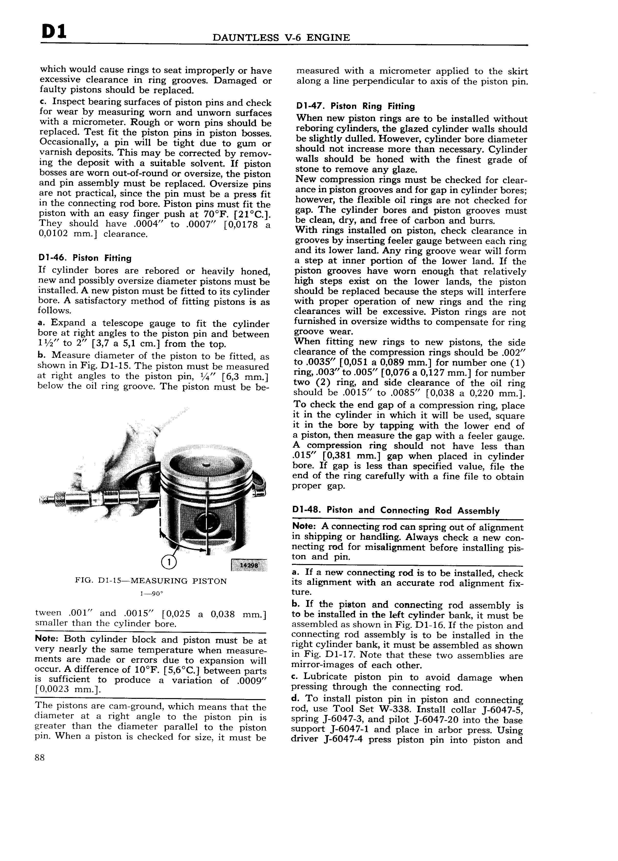
D1 DAUNTLESS V 6 ENGINE which would cause rings to seat improperly or have measured with a micrometer applied to the skirt excessive clearance in ring grooves Damaged or along a line perpendicular to axis of the piston pin faulty pistons should be replaced c Inspect bearing surfaces of piston pins and check Di 47 pision Ring Fitting for Wear by measuring wom and umivom surfaces When new piston rings are to be installed without wu a imSIf0mi t r hR ligh Of won puist shoggd be reboring cylinders the glazed cylinder walls should gp ac nest It t B tiistgn Rm lg pls On sS s be slightly dulled However cylinder bore diameter Ccqsfr a y a tgglfwl 8 ug t uedtg gum Or should not increase more than necessary Cylinder Val ms pOS1ts ls may b com ecte y relnow walls should be honed with the finest grade of ing the deposit with a suitable solvent If piston Stone to remove any giozo bozses are wO glOut Of r0 nd Oli Ov Slg th piston New compression rings must be checked for clear tm pm assem Y inust 6 nip ace vetslze puts ance in piston grooves and for gap in cylinder bores ere not pmcmiah Smce the pin must be a preiss ht however the flexible oil rings are not checked for in the connecting rod bore Piston pinsomust fit the gap The cylinder bores and piston grooves must piston with an easy finger push at 70 F 21 C b i d d f f boo od buns They should have 0004 to 0007 0 0178 e a t an a o 0102 mm clearance With rings installed on piston check clearance in grooves by inserting feeler gauge between each ring and its lower land Any ring groove wear will form Dl 46 Piston Fitting a step at inner portion of the lower land If the If cylinder bores are rebored or heavily honed piston grooves have worn enough that relatively new and possibly oversize diameter pistons must be high steps t Oh the lower 16hdS fh Piston installed A new piston must be fitted to its cylinder h0 ld be Yeplaced b 8U the Steps will interfere bore A satisfactory method of fitting pistons is as viirth PTOPBF i9 8U0h 0f h WP hg Qhd the Tmg fO OwS c earances wi e excessive iston rings are not a Expand 8 toiosoopo gouge to fit the Cylinder furnished in oversize widths to compensate for ring bore at right angles to the piston pin and between gt V Yvgan 1 to 2 3 7 8 5 1 cm from tho top When fitting new rings to new pistons the sid b M d t f h t t b tt d clearance of the compression rings should be 002 eaisure lame er O t 8 pls On O 8 1 Q as to 0035 0 051 a 0 089 mm for number one 1 shown in Fig D1 l5 The piston must be measured ring 003 to 005 0 076 a 0 127 mm for number 1 ghthe gi S to the img P t f6 bmf l two 2 hhg and side Cl 8l 3I1C er the oil ring 8 OW t Q mg g 9 P S mus 6 should be 0015 to 0085 0 038 e 0 220 mm To check the end gap of a oompression ring place it in the cylinder in which It will be used square it in the bore by tapping with the lower end of a piston then measure the gap with a feeler gauge A compression ring should not have less than 4 015 0 381 mm gap when placed in cylinder iff Q I i bore If gap is less than specified value file the ng A end of the ring carefully with a fine file to obtain se 8 7 e c a 2 2 i Pepe gee ii a e 2 e i5 1 e Z ei i d Connectin Rod Assembl in ininli V i i ori iii 3 D I 48 Piston an g y l Z i I Notei Aiconnecting rod can spring out of alignment i IH ship ing or handling Always check a new con P d f 1 b f H i necting ro or misa ignment e ore insta 1ng pis Voiio ton and pin a If a new connecting rod is to be installed check FIG Dl l5 MEASURING PISTON its alignment with an accurate rod alignment fix i 9O ture b If the piston and connecting rod assembly is tween OO1 and 0015 0 025 a 0 038 nnn to be installed in the left cylinder bank it must be smaller than the Cylinder bO1 assembled as shown in Fig D1 l6 If the piston and connecting rod assembly is to be installed in the N t Both yl d r block and piston must be at right cylinder bank it must be assembled as shown Very neatly the Same temperature when ttl aSut in F ig D1 17 Note that these two assemblies are ments Xrgzlfinade or feigoiiis doiegoz eocpansion will mirmnimagos of each Othon Qccun 1 treme O etween partg c Lubricate piston pin to avoid damage when is sufficient to produce a variation of 0009 pressing through the Connecting md 0 0023 d To install piston pm in piston and connecting The pistons are cam ground which means that the rod use Tool Set W 338 Install collar 6047 5 diameter at a right angle to the piston pin is spring 6047 3 and pilot 6047 20 into the base greater than the diameter parallel to the piston support 6047 1 and place in arbor press Using pin When a piston is checked for size it must be driver 6047 4 press piston pin into piston and 88