Ford Parts Wiki | GM Parts Wiki
Home | Search | Browse | Marketplace | Messages | FAQ | Guest
Prev

 Next
Next
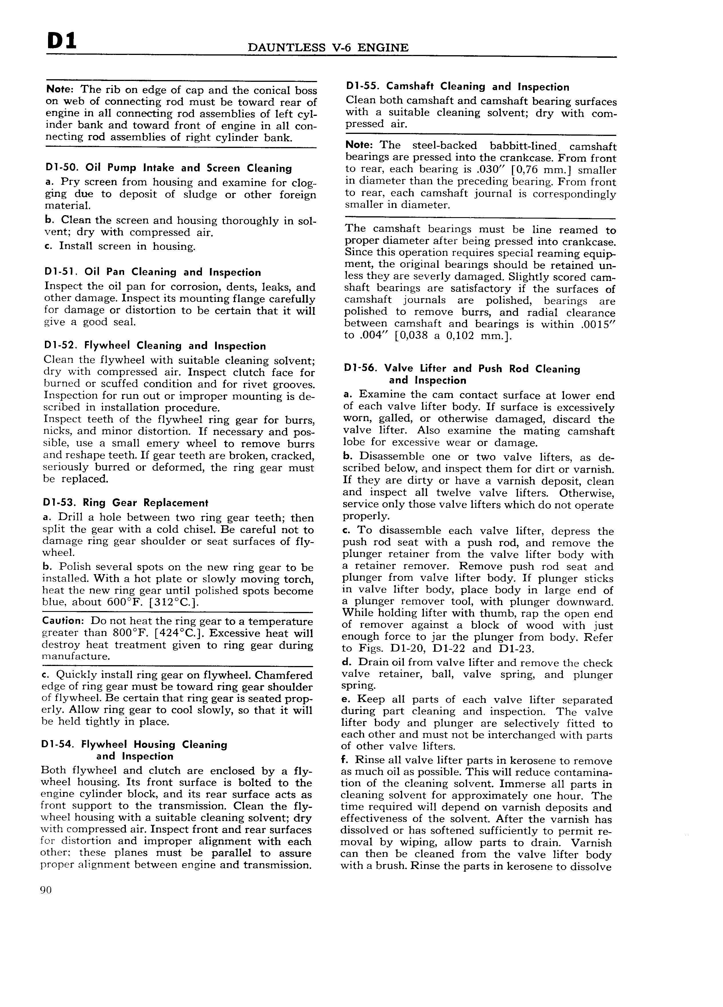
D 1 DAUNTLESS V 6 ENGINE Note The rib on edge of cap and the conical boss Dl 55 Camshaft Cleaning and p di on web ot connecting tod must bo toward mai of Clean both camshaft and camshaft bearing surfaces engine in all connecting rod assemblies of left cyl Wlm a Snrrablo oloanmg Solvent dry Wlm oom inder bank and toward front of engine in all con Prossad alr d l Nm The st l b k d b bb tt r l camshaft bearings are pressed into the crankcase From front DI 50 Oil Pump Intake and Screen Cleaning to rear each bearing is 030 0 76 mm smaller at pty Screen from housing and examine oi oiog in diameter than the preceding bearing From front ging due to deposit of sludge or other foreign to raaryoagn oamsnarr Journal ls oorrospondlngly matotiai sma er in iameter b Cl h d h h hl vent 3 1ytv t r sS 3u i t Omug y m SOI The Camshaft b armgstmust be line reamgd to I t H Screen in housin proper diameter after being pressed into crankcase c ns a g Since this operation requires special reaming equip ment the original bearings should be retained un Dl 5l O Pan Cl9am 9 and l P Cl less they are severly damaged Slightly scored cam Inspect the oil pan for corrosion dents leaks and shaft bearings are satisfactory if the surfaces of other damage Inspect its mounting flange carefully camshaft journals are polished bearings are for damage or distortion to be certain that it will polished to remove burrs and radial clearance give a good seal between camshaft and bearings is within 00l5 to 004 0 038 a 0 102 mm DI 52 Flywheel Cleaning and Inspection Clean the flywheel with suitable cleaning solvent dry with compressed air Inspect clutch face for D S6 valzielhher and Push Rod Cleamng burned or scuffed condition and for rivet grooves an nspedmn Inspection for run out oi imotopoi mounting is do a Examine the cam contact surface lat lowers end scribed in installation proceduret of each valve lifter body If surface is excessively Inspect teeth of the flywheel ring gear for burrs Worn sailed 0f otnorwrso damagedi dlsoard tho nicks and minor distortion If necessary and pos valve llrror Also oxamlno ma matlng Camshaft sible use a small emery wheel to remove burrs lobo for oxoosslvo Woar or damage and reshape teeth If gear teeth are broken cracked b Disassemble one or two valve lifters as de seriously burred or deformed the ring gear must scribed below and inspect them for dirt or varnish be replaced If they are dirty or have a varnish deposit clean and inspect all twelve valve lifters Otherwise DI 53 Ring Gear Replacement service only those valve lifters which do not operate a Drill a hole between two ring gear teeth then ProPorlY split the gear with a cold chisel Be careful not to c To disassemble each valve lifter depress the damage ring gear shoulder or seat surfaces of fly push rod seat with a push rod and remove the wheel plunger retainer from the valve lifter body with b Polish several spots on the new ring gear to be a roramor romoV r Remove Push rod Soar and installed With a hot plate or slowly moving torch p1 g r frgvm valve llrror bodY If Plungor Snoks heat the new ring gear until polished spots become ln valve llrtor b dy Plaoo body ln large and of blue about 6 F 312 C alvplpnlgletdrempyer took vtzlith lplungenq downwarg ie o ingiterwit tum rapteopenen Caution Do not heat the ring gear to attemperature of tomovot against a block of Wood with just graatar than 80001 l424 C l Excessrve naar Vfnll enough force to jar the plunger from body Refer destroy heat treatment given to ring gear during to Figs D1 g Digg and D1 23 manufacture d Drain oil from valve lifter and remove the check c Quickly install ring gear on flywheel Chamfered ValY retainer ball valve Sprmgr and plunger edge of ring gear must be toward ring gear shoulder Prmg of flywheel Be certain that ring gear is seated prop e Keep all parts of each valve lifter separated erly Allow ring gear to cool slowly so that it will during part cleaning and inspection The valve be held ti htly in lace lifter body and plunger are selectively fitted to eac ot er an must not einterc ange wit parts g P h h d b h d h DI 54 Flywheel Housing Cleaning of other valve lifters and l PoCll n f Rinse all valve lifter parts in kerosene to remove Both flywheel and clutch are enclosed by a fly as much oil as possible This will reduce contamina wheel housing Its front surface is bolted to the tion of the cleaning solvent Immerse all parts in engine cylinder block and its rear surface acts as cleaning solvent for approximately one hour The front support to the transmission Clean the fly time required will depend on varnish deposits and wheel housing with a suitable cleaning solvent dry effectiveness of the solvent After the varnish has with compressed air Inspect front and rear surfaces dissolved or has softened sufficiently to permit re for distortion and improper alignment with each moval by wiping allow parts to drain Varnish other these planes must be parallel to assure can then be cleaned from the valve lifter body proper alignment between engine and transmission with a brush Rinse the parts in kerosene to dissolve 90

 Next
Next