Ford Parts Wiki | GM Parts Wiki
Home | Search | Browse | Marketplace | Messages | FAQ | Guest
Prev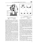
 Next
Next
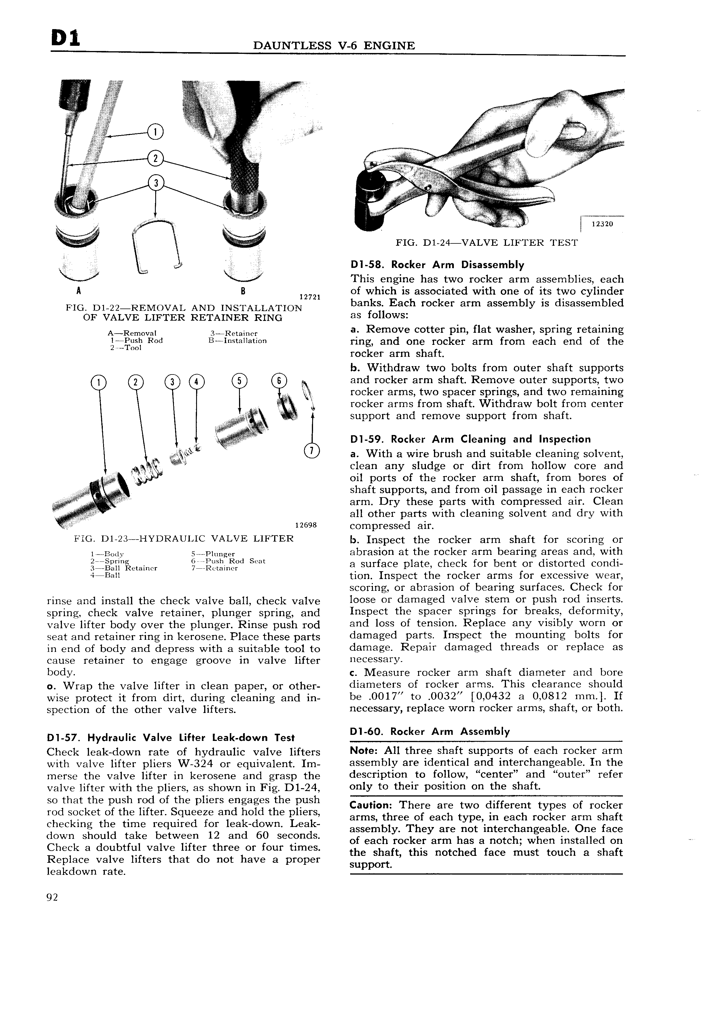
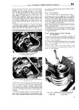
D 1 DAUNTLESS V 6 ENGINE gl i i i V E i ii i V iv In 1 fl A U A V L A zx E A E E V A T V 2 E I v VA sig I VV v i V si j E V I QQ V V 2 n n i a J V aAV A 6 V V V T V V E 3 Y AA V il fi 0 Ufff gi V v H 2 i e A 5A A A Q A V V ii E z A V V h M E r FIG D1 24 VALVE LIETER TEST ef i D I 58 Rocker Arm Disassembly This engine has two rocker arm assemblies each A B 12721 of which is associated with one of its two cylinder HG D1 22 REMOVAL AND INSTALLATION banks Each rocker arm assembly 1S disassembled or VALVE LIFTER RETAINER RING es f U WS A R mOval 3 R mhm a Remove cotter pin flat washer spring retaining igzl Red B i Sr ll i ring and one rocker arm from each end of the rocker arm shaft b Withdraw two bolts from outer shaft supports Q y and rocker arm shaft Remove outer supports two rocker arms two spacer springs and two remaining rocker arms from shaft Withdraw bolt from center i if support and remove support from shaft J I j j 5 D 59 Rocker Arm Cleaning and Inspection a il a With a wire brush and suitable cleaning solvent clean any sludge or dirt from hollow core and oil ports of the rocker arm shaft from bores of shaft supports and from oil passage in each rocker l arm Dry these parts with compressed air Clean all other parts with cleaning solvent and dry with 12698 compressed air FIG D1 23 HYDRAULI VALVE LIFTER b Inspect the rocker arm shaft for scoring or 1 Barry S Plunger abrasion at the rocker arm bearing areas and with j Q cm mr Qf n d S a surface plate check for bent or distorted condi 4 B l1 tion Inspect the rocker arms for excessive wear scoring or abrasion of bearing surfaces Check for rinse and install the check Valve ball cheek valve loose or damaged valve stem or push rod inserts Spring Cheek Valve retainer plunger Spring and Il 1Sp Ct tll Sp3C X Sp1 1I 1gS fO1 l3I 2il S Cl fOI 1 T11ty Valve lifter body over the plunger Rinse push red and loss of tension Replace any visibly worn or seat and retainer ring in kerosene Place these parts damaged parts Inspect the mounting bolts for in end Of bgdy and depress with ei suitable reel re damage Repair damaged threads or replace as cause retainer to engage groove in valve lifter HBCQSSQYY body c Measure rocker arm shaft diameter and bore 0 Wrap the valve lifter in clean paper or Other diameters of rocker arms This clearance should wise protect it from dirt during cleaning and in be 0017 to 0032 I 0 0432 8 0 0812 mm If speerieri gf the other valve lifters necessary replace worn rocker arms shaft or both 5 H valve Lifter tak w ra Cheek leak down rate of hydraulic valve lifters N fe A11 three Sheff supports of each rocker arm with valve lifter pliers W 324 Or equivgilerit Im assembly are identical and interchangeable In the merse the valve lifter in kerosene and grasp the d SC1 ipti0 t0 follow center and 0uter refer Valve lifter with the pliers as shown in Fig Dl 24 only te th 1Y P0SlU0 OU the shaft Soghatlfhs Of h pl1 rSHE l a Stl h lush Caution There are two different types of rocker rg TC ets t I an gugcie al kod e IiI lE arms three of each type in each rocker arm shaft 5 ec 13 mis rgqtmre X ad syn aj assembly They are not interchangeable One face Czwnk 5 gu bttfa le le wizil th an f Seilm S of each rocker arm has a notch when installed on QC 3 Ou Ll Va Ve I er me Or Our 1m S the shaft this notched face must touch a shaft Replace valve lifters that do not have a proper support leakdown rate 92