Ford Parts Wiki | GM Parts Wiki
Home | Search | Browse | Marketplace | Messages | FAQ | Guest
Prev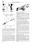
 Next
Next
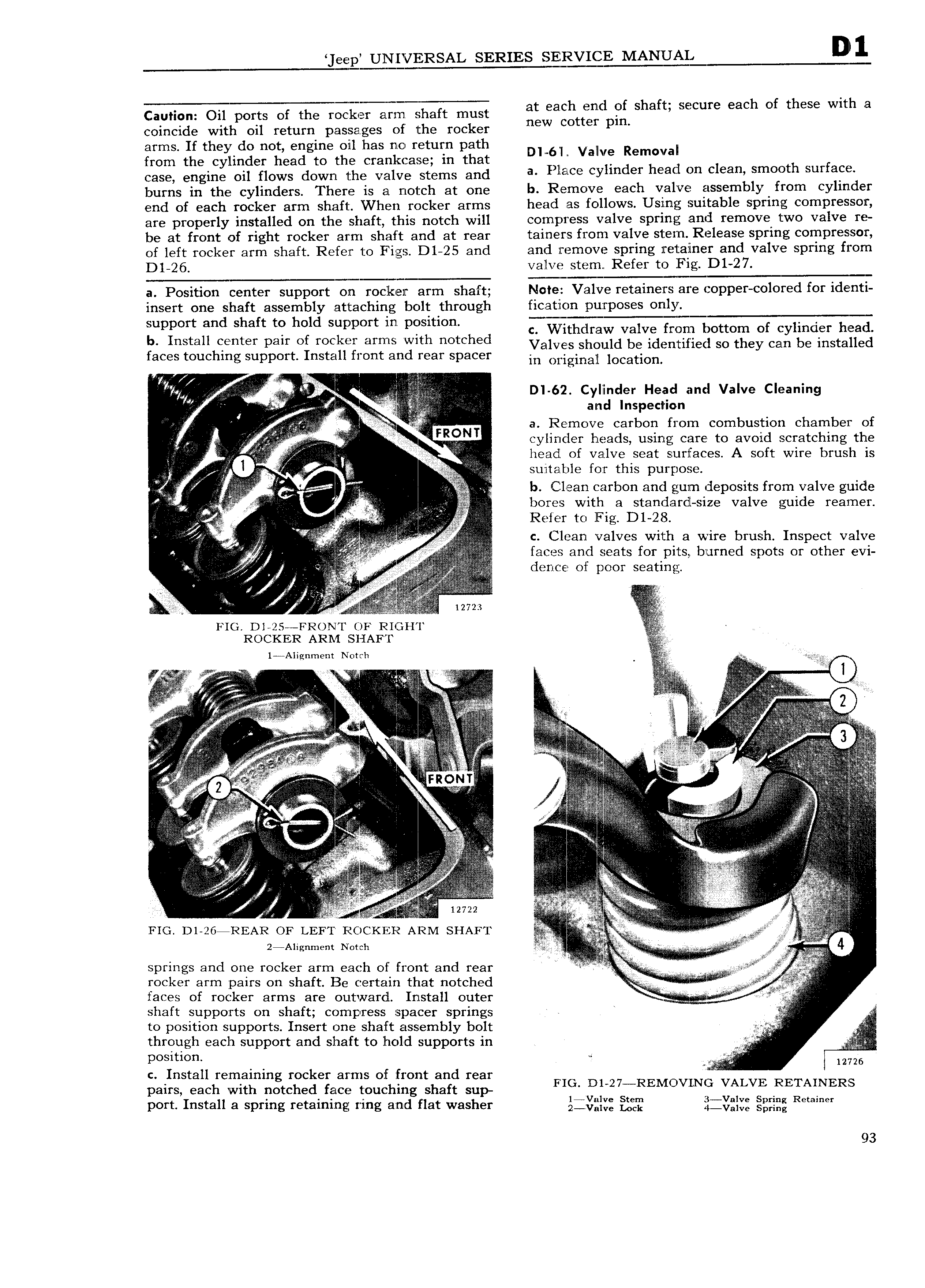
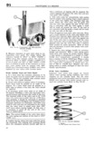
T l eep UNIVERSAL SERIES SE I2VI E MANUAI D 1 i I h h f th ith Cauhon Oil ports of the rocker arm shaft must a lgtf 1 S aft qecure Bac O ese W a coincide with oil return passages of the rocker p arms If theyAdo not engine oil has no return path D1AA6 A vauve Removal from the cylinder head to the crankcase in that A A h f CQSBA engine Oil flows down the Valve Stems and a I lace cylinder head on clean smoot sur acc burns in the cylinders There is a no1 ch at one b Remove each valve assemblyAfrom cyl1n der end of each rocker arm shaft When rocker arms head as follows Using suitable spring compressor are properly installed on the shaft this notch will compress valve spring and remove two valve re be at front of right rocker arm shaft and at rear tamers from valve s1 em AARelease spring compressor of left rocker arm shaft Refer to Figs D1 25 and and remove spring retainer and valve spring from Dl 26 valve stem Refer to Fig D1 27 a Position center support on rocilneir arm shaft Note Valve retainers are copper colored for identi insert one shaft assembly attaching bolt through ficatcion purposes only t d h ft h ld T I quppor an S 8 tg 0 support m p ismon c Withdraw valve from bottom of c linder head bIt1l t 2k2 th thd y f HS 3 hqm er paul OI mCl mlS gl no C 6 Valves should be identified so they can be installed aces touc mg support nstal iont an rear spacer in Ofiginajl location l A A i ai I D 62 Cylinder Head and Valve Cleaning T V AA r A I and Inspection V i V a Remove carbon from combustion chamber of i t t I FRONT 2 AI A V cylinder heads using care to avoid scratching the Aj f I A It l I AAA head of valve seat surfaces A soft wire brush is 2 I E suitable for this purpose A ff i A b Clean carbon and gurn deposits from valve guide A V bores with a standardl size valve guide reamer 1 3 V Refer to Fig D1 28 2 2 i I I i rr 4 c Clean valves with a wire brush Inspect valve rr j I V A it faces and seats for its burned s ots or other evi I V Z I d f p C t I 0 pw S s 2 I i L V V J t N 12723 V FIG Dl 25 FR N l OF RIGHT I ROCKER ARIVI SHAFT l Alignment Notch A A iYA A VV E V IV I E if at r z I i I f F 2 QV V i M Q Zii E i i V an I ii 2 e V V a 5 V In V II Ei V 2 V r i ii i A i V 2 j V i i r f i i if r V i izi 9 i VV V VV tr F I r t i a inV fi r r riVeV t r Q i 2 I c V V I I FR Y IVV I 2 if I I I L I I I is V IV II V i fi I V I I A A IA A Igln A cx A VrV AAA AA V I II t I V J IrII V V I 2 I I I V tVt VV I l i i I I li I l ai I s i V V sa I z V Y V 2 2 V 2i 2 2 I 1 1 l f z i Q 7 i I a Tl I n I I I I i iiE V y e V V f I I 2 2 E 2722 II VIV 522 2 II V 2 IVI l I I 3 2 I F I i FIG D1 26 REAR OF LEFT ROcK 2 R ARM s1 AFT VVV V2 2 II Aj T 2 Allg m Y N 0l Ch V springs and one rocker arm each of front and rear I ili A A AAAA A rocker arm pairs on shaft Be certain that notched II AA AAAAA A i V i faces of rocker arms are outward Install outer rtf V shaft supports on shaft compress spacer springs to position supports Insert one shaft assembly bolt e e i A Z through each support and shaft to hold supports in W ii VV I i position 0 A AAAA A Vf c Install remaining rocker arms of front and rear FI I E pairs each with notched face touching shaft sup L i 27 REMOV LN VALVh RETAINERS port Install a spring retaining ring and flat washer 2 v ll Z LEE ii viZiY Z ggiix Rmlnu 93