Ford Parts Wiki | GM Parts Wiki
Home | Search | Browse | Marketplace | Messages | FAQ | Guest
Prev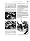
 Next
Next
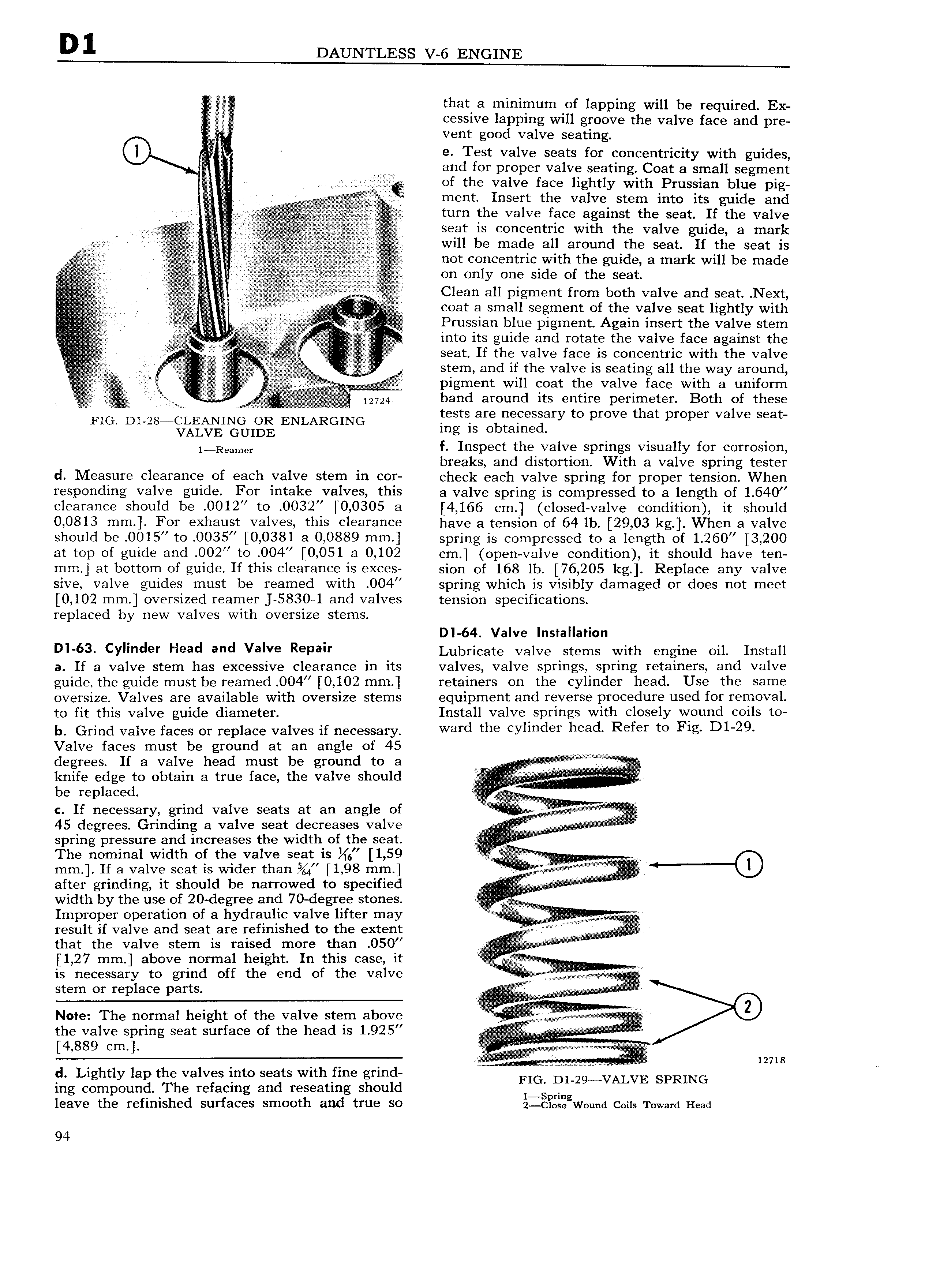
E that a minimum of lapping will be required Ex I cessive lapping will groove the valve face and pre vent good valve seating lf e Test valve seats for concentricity with guides and for proper valve seating Coat a small segment 0 lll of the valve face lightly with Prussian blue pig Ilxglig ment Insert the valve stem into its guide and turn the valve face against the seat If the valve y j seat is concentric with the valve guide a mark gecg is Wlll be made all around the seat If the seat is 110t COHCeHtf1C Wlth the guide a mark will be made 0 00 00lY 000 000 0f 000 0000 Clean all pigment from both valve and seat Next A i E C0a C a Small Segment of the valve seat lightly with I V i 3 i Prussian blue pigment Again insert the valve stem s into its guide and rotate the valve face against the A r f seat If the valve face is concentric with the valve t ii 1 0000 000 if the Valve is seams all the Way around Y i I E E li E El 0igm00t will 000 00 V0lV0 000 with 0 000000 isnn 0 iiii 12724 band around 1tS 9 flI p I 1I1 1 T I Both of these FIG D1 28 Igli lgi ENLARGING Sarsbrcigieggary to prove that proper valve seat lmngamc f Inspect the valve springs visually for corrosion breaks and distortion With a valve s rin tester d Measure clearance of each valve stem in cor check each valve spring for proper tengiong When responding valve guide For intake valves this a valve spring is compressed to a length of 1 640 Clearance Should be 0012 to 0032 0 0305 a 4 166 cm closed valve condition it should 0 0813 mm For exhaust valves this clearance have 3 tension of 64 lb 29 03 kg When a valve should be 0015 to 0035 0 0381 a 0 0889 mm spring is compressed to a length of 1 260 3 200 at top of guide and 002 to 004 0 051 a 0 102 cm open valve condition it should have ten mm at bottom of guide If this clearance is exces sion of 168 lb 76 205 kg Replace any valve sive valve guides must be reamed with 004 spring which is visibly damaged or does not meet 0 102 mm oversized reamer J 5830 1 and valves tension specifications replaced by new valves with oversize stems D1 64 Valve Installation Dl 63 CYll d9r Head and valve RBPal Lubricate valve stems with engine oil Install a If a valve stem has excessive clearance in its valves valve springs spring retainers and valve guide the guide must be reamed OO4 0 102 mm retainers on the cylinder head Use the same oversize Valves are available with oversize stems equipment and reverse procedure used for removal to fit this valve guide diameter Install valve springs with closely wound coils to b Grind valve faces or replace valves if necessary ward the CYll d Y h 3d Refer to F1g 131 29 Valve faces must be ground at an angle of 45 degrees If a valve head must be ground to a Kg M 1 edge tO 3 true face th Valve be replaced c If necessary grind valve seats at an angle of r V l l L Z P 45 degrees Grinding a valve seat decreases valve Slzlrlng Pi UI 81 ld increases the width Of the Seat r 0 The nominal width of the valve seat is 6 1 59 V mm If a valve seat is wider than 4 1 98 mn 00 rA I after grinding it should be narrowed to specified v z r l width by the use of 20 degree and 70 degree stones Improper operation of a hydraulic valve lifter may iiilnl l result if valve and seat are refinished to the extent r I l V 4 that the valve stem is raised more than O50 il 1 27 mm above normal height In this case it v is necessary to grind off the end of the valve l stem or replace parts V A N0te The normal height of the valve stem above G i the valve spring Seat surface of the head is 1 925 E A 4 889 cm r l M Q r v I 12718 d Lightly lap the valves into seats with fine grind if ALVE SPRING ing compound The refacing and reseating should leave the refinished surfaces smooth and true so jl x gW0und Cons Toward Head 94