Ford Parts Wiki | GM Parts Wiki
Home | Search | Browse | Marketplace | Messages | FAQ | Guest
Prev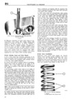
 Next
Next
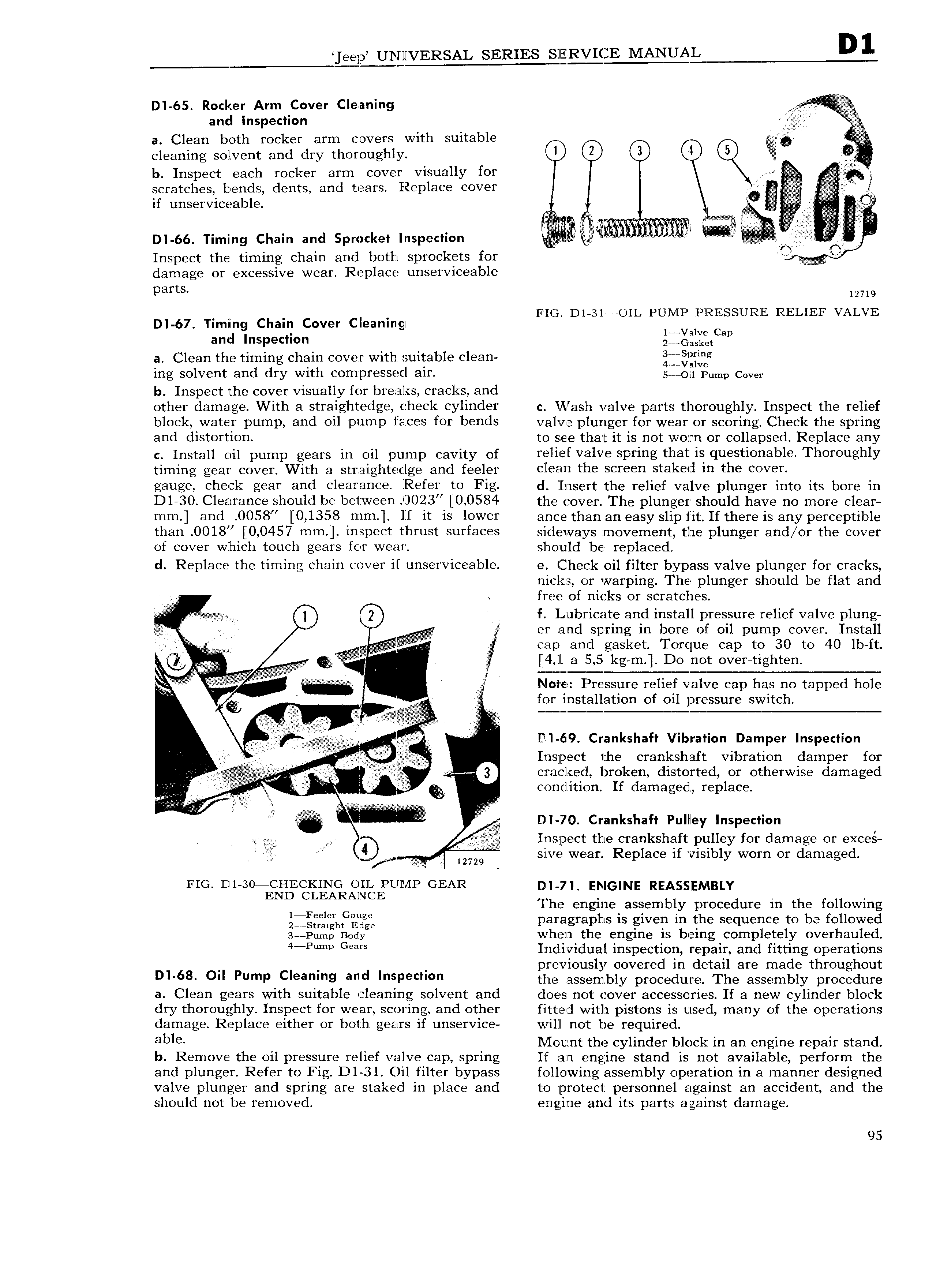
eep UNIIVERSAL SERIES SERVICE MANE I D1 65 Rocker Arm Cover Cleaning I and Inspection 5 a Clean both rocker arm covers with suitable cleaning solvent and dry thorouglnly t l ez 3 4 if b Inspect each rocker arm cover visually for scratches bends dents and tears Replace cover if unserviceable r l A llroer s c r r DI 66 Timing Chain ancl Sprocket Inspection Inspect the timing chain and both sprockets for damage or excessive wear Replace unserviceable parts 12719 FIQ Dl 31 4OIL PUI IP PRESSURE RELIEF VALVE DI 67 Timing Chain Cover Cleanlnign J V and inspeaaon c g i a a Clean the timing chain cover with suitable clean i E ing solvent and dry with compressed air sv 0 Pump cover b Inspect the cover visually for breaks cracks and other damage With a straiglitedge check cylinder c INash valve parts thoroughly Inspect the relief block water pump and oil pump faces for bends valve plunger for wear or scoring Check the spring and distortion to see that it is not worn or collapsed Replace any c Install oil pump gears in oil pump cavity of relief Valve spring that is questionable Thoroughly timing gear cover With 3 s tr aightedge and feeler clean the screen staked in the cover gauge check gear and clearance Refer to Fig d llnsert the relief valve plunger i nto its bore in D1 30 Clearance should be between 0023 0 0584 the cover The plunger should have no more clear mm and 0058 0 1358 Mmm If it is lower ance than an easy slip fit If there is any perceptible than 0018 0 0457 mm rnspect thrust surfaces sideways movement the plunger and or the cover of cover which touch gears for wear should be replaced cl Replace the timing chain cover if unserviceable e Check oil filter bypass valve plunger for cracks nick s or warping The plunger should be flat and 4 l free of nicks or scratches 0 0 A f Lnbricate and install pressure relief valve plung er and spring in bore of oil pump cover Install V i cap and gasket Torque cap to 30 to 40 lb ft px A Q 4 a 5 5 kg m Do not over tigh1 en Note Pressure relief valve cap has no tapped hole 2 Z for installation of oill pressure switch U DI 69 Crankshaft Vibration Damper Inspection V Inspect 1 he crankshaft vibration damper for V Vllv Q cmcl ed broken distorted or otherwise damaged E condition If damaged replace at D1 70 Crankshaft Pulley Inspection Inspect the crankshaft pulley for damage or exces G W si 127 i sive wear Replace if visibly worn or damaged Q FIG D1 30 CHECKIN G OIL PUNIP GEAR END CLEARANCE D I 71 EI IGINE REASSSENIBLY U Ihe engine assembly procedure in the following igffgfghfggfc paragraphs is given in the sequence to be followed za Pump Body when the engine is being completely overhauled 4 P Gem Individual inspection repair and fitting operations previously covered in detail are made throughout Dl 68 O PumP Cl a I 9l and jP the assembly procecluzre The assembly procizdure a Clean gears with suitable cleaning solvent and does not cover accessories If a new cylinder block dry thoroughly Inspect for wear scoring and other fitted with pistons is used many of the operations damage Replace either or both gears if unservice will not be required zbli th 1 l f 1 vlount the cylinderi block in an ingifne repgir stand emove e oi pressure re ie va ve cap spring r an engine stani is not avai a e per orm the and plunger Refer to Ii 1g D1 3l Oil filter bypass following assembly operation in a manner designed valve plunger and spring are staked in place and to protect personnel against an accident and the should not be removed engine and its parts against damage 95