Ford Parts Wiki | GM Parts Wiki
Home | Search | Browse | Marketplace | Messages | FAQ | Guest
Prev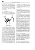
 Next
Next
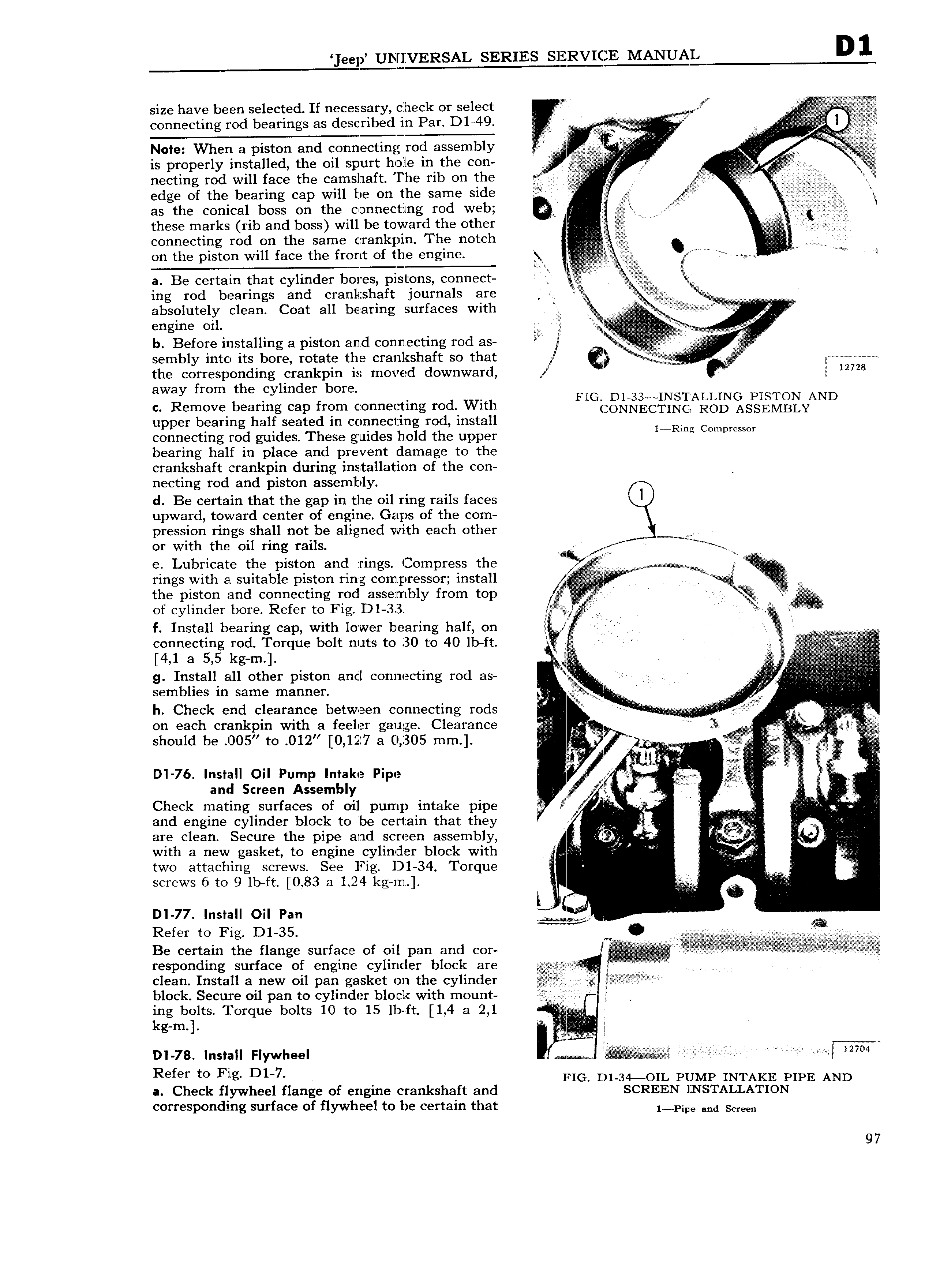
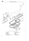
eep UNIVERSAL SERIES SIIQIREQSZE MANU size have been selected If necessary check or select V fi connecting rod bearings as described in Par D1 49 yy gg I l V V Note When a piston and connecting rod assembly N M is properly installed the oil spurt hole in the con rr v v I necting rod will face the camshaft The rib on the I L T i Bil edge of the bearing cap will be on the Same side A if ii rrii ZX as the conical boss on the connecting rod web v F gj these marks rib and boss will be toward the other I I connecting rod on the same crankpin The notch H V on the piston will face the front of the engine X A Mee Q a Be certain that cylinder bores pistons connect ig ing rod bearings and cranl shaft journals are V M A absolutely clean Coat all t al i g Surfaces Q c g engine Oil S VV S S b Before installing a piston and connecting rod as sembly into its bore rotate the crankshaft so that l nn Z iii 1 Tl v iii J e the corresponding crankpin is moved downward lizm my from the mde Ne DI 33 IN T ALLING NWN AND c Remove bearing cap from connecting rod With r ON EE I IfQ G RQOD ASSEMBLY upper bearing half seated in connecting rod install connecting rod guides These guides hold the upper 1 I g C mpr Ss r bearing half in place and prevent damage to the crankshaft crankpin during installation of the con necting rod and piston assembly d Be certain that the gap rin the oil ring rails faces upward toward center of engine Gaps of the com pression rings shall not be aligned with each other or with the oil ring rails S egg e Lubricate the piston and rings Compress the rings with at suitable piston ring compressor install ww I H the piston and connecting rod asseimbly from top A I of cylinder bore Refer to Fig D1 33 t 4 2 f Install bearing cap with lower bearing half on 2 connecting rod Torque bolt nuts to 30 to 40 lb ft r N Ti 4 1 a 5 5 kg m iT g Install all other piston and connecting rod as ii I I A semblies in same manner I h Check end clearance between connecting rods ii N i I on each crankpin with a feeler gauge Clearance r Et should be O05 to 012 0 127 a 0 305 mm S l Q Y fl i DI 76 Install Oil Pump Intake Pipe I ix I ii I and Screen Assembly 1 Check mating surfaces of oil pump intake pipe j f s if I i i 2 W j I and engine cylinder block to be certain that they A t P M i are clean Secure the pipe and screen assembly A f f with a new gasket to engine cylinder block with g V rl i i ij two attaching screws See Fig D1 34 Torque l screws 6 to 9 lb ft 0 83 a 1 24 kg in V L 7 li I It l I DI 77 Install Oil Pan j I Refer to Fig D1 35 T M C E S W V yrlq Q VM Be certain the flange surface of oil pan and cor responding surface of engine cylinder block are 1 i i E iii i E iii I clean Install a new oil pan gasket on the cylinder S block Secure oil pan to cylinder block with mount if ing bolts Torque bolts 10 to 15 ll ft 1 4 a 2 1 i I kg m 6 nl 78 Install Flywheel a e I I l Y Refer 0 Fig D1 7 FIG D1 34 OIL PUMP INTAKE PIPE AND a Check flywheel flange of engine crankshaft and SCREEN INSTALLATION corresponding surface of flywheel to be certain that 1 p p e and scmn 97