Ford Parts Wiki | GM Parts Wiki
Home | Search | Browse | Marketplace | Messages | FAQ | Guest
Prev
 Next
Next
994757
994757
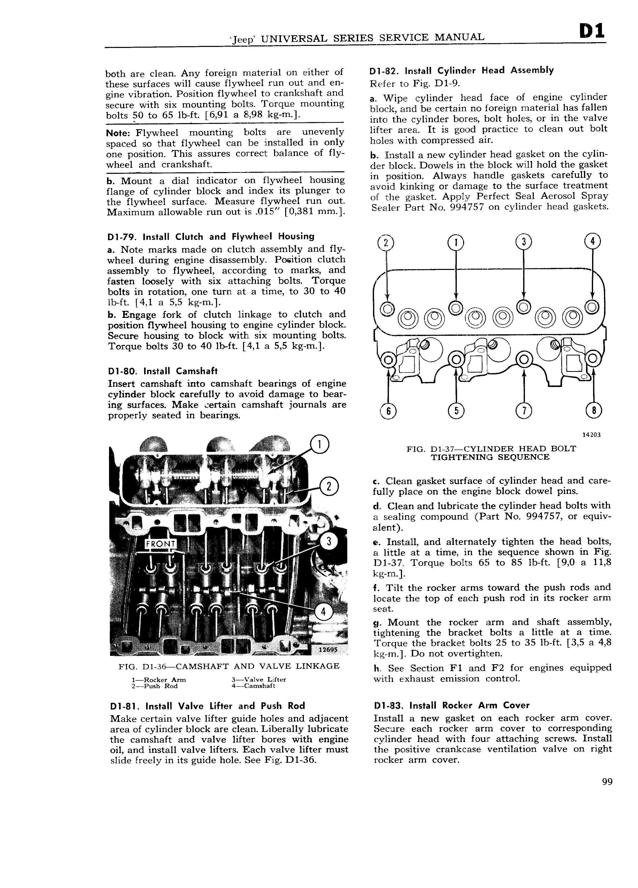
eep UPEIYERSAL SERIES MANUAL both are clean Any foreign rn ateri a l on either of DI l 3 2 Install Cylinder Head Assembly these surfaces will cause flywheel run out and en Rgfer O Fig D1 Q gine vibration Position flywlrieel to crankshaft and a Ni pe cylinder htad face of engine cylinder ieiltlresgqch Eungiggl b lgYb 8l rgl mmmtmg block and be certain no foreign material has fallen O S 0 Q i L M into the cylinder bores bolt holes or in the valve Note Flywheel mounting bolts are unevenly lifter area It is good practice to clean out bolt spaced so that flywheel can be installed in only h 1 2 vv1thic0m1 r SS i air Oiis Position This assuiss Correct balance Of fly b llnstall a new cylinder head gasket on the cylin Wheel and crankshaft der block Dowels in the block will hold the gasket b Mount a dial indicator on flywheel housing III YP OS tl n Alwzyi llaudle gasket carefully Ito fl3Hg of CyllHCl 1 bl0Ck and index its plunggy O 3VO i Zi kinklng 0I 3lI 1dg to 8 Sur ace treattngnt the flywheel Surface M aSu flywhpel nm Out of the gasket Apply Perfect Seal Aerosol Spray Maximum auowableifun Out ig 015 6 381 mm Sealer Part No 994757 on cylinder head gaskets DI 79 Install Clutch and Flywheel Housing lx Z a Note marks made on clutch assembly and fly J wheel during engine disassembly Position clutch assembly to flywheel according to marks and fasten loosely with six attaching bolts Torque bolts in rotation one turn at a time to 30 to 40 lb ft 4 1 a 5 5 kg m b Engage fork of clutch linkage to clutch and 9 O O position flywheel housing to engine cylinder block r xg Secure housing to block with six mounting bolts Torque bolts 30 to 40 lbft 4 1 Ei 5 5 kg m C O C 6 o G Q B DI 80 Install Camshaft C in Insert camshaft into camshaft bearings of engine r f cylinder block carefully to avoid damage to bear ing surfaces Make certain camshaft journals are 1 p properly seated in bearings l Ll ID 8 i i 3 i f e FIG D1 37 YL1NDER HEAD BOLT VV I 2 TK ITiEi NING SEQUENCE I V ii c Clean gasket surface of cylinder head and care V fully place on the engine block dowel pins ilili Q E Eiiizlii V cl Clean and lubriiccate the cylinder head bolts with ii i Q C I y i a sealing compound Part No 994757 or equiv X 5 Q M N alenlt Il M 9 I e Install and alternately tighten the head bolts V L fg a little at a time in the sequence shown in Fig gb ii D1 37 Torque bolts 65 to 85 lb ft 9 0 a 11 8 i I S ZE i v kg rn el i i 1 I f Tilt the rocker arms toward the push rods and Q 4 E i I 5 i I t locate the top of each push rod in its rocker arm A i i S gi g lV o unt the rocker arm and shaft assembly J tightening the bracket bolts a little at a time V r 12645 Torque the bracket bolts 25 to 35 lb ft 3 5 3 4 8 ii i r s i z l I kg rn Do not overtighten FIG Dl 36 CAMSHAFT AND VALVE LINKAGE lr See Section F1 and F2 for engines equipped 1 oc re Airm 2 galveh Iiigtcr Wlljll Xll BL1St GITIISSIOITI COI tI OI US O 2 l lS 3 DI 81 Install Valve Lifter and Push Rod DI 183 Install Rocker Arm Cover Make certain valve lifter guide holes and adjacent Install a new gasket on each rocker arm cover area of cylinder block are clean Liberally lubricate Sectire each rocker arm cover to corresponding the camshaft and valve lifter bores with engine cylinder head with four attaching screws Install oil and install valve lifters Each valve lifter must the positive cranlccase ventilation valve on right slide freely in its guide hole See Fig D1 36 rocker arm cover 99