Ford Parts Wiki | GM Parts Wiki
Home | Search | Browse | Marketplace | Messages | FAQ | Guest
Prev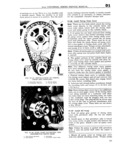
 Next
Next
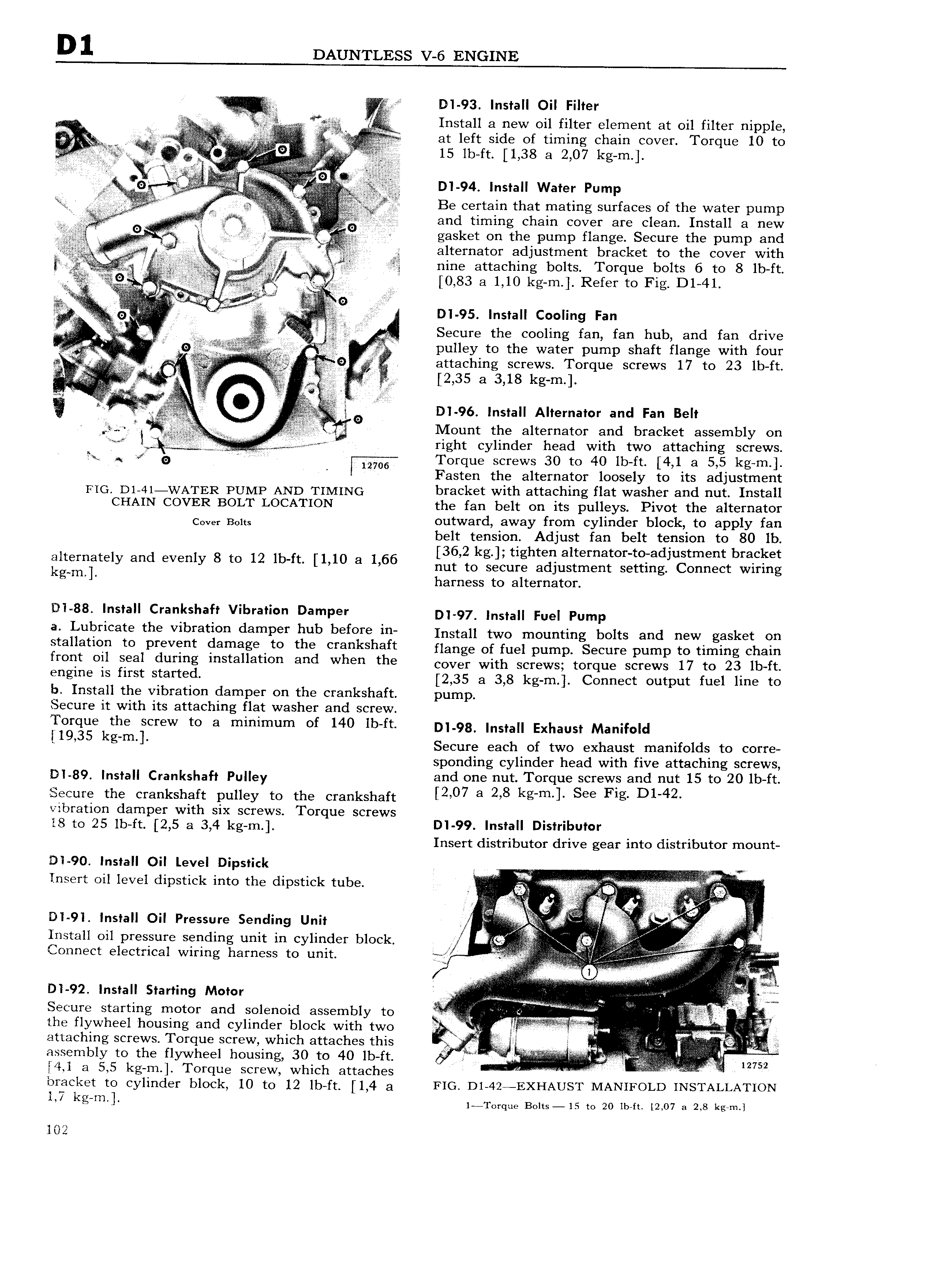
D 1 DAUNTLESS V 6 ENGINE I A V a ZZ I DI 93 Install Oil Filter i I Q Install a new oil filter element at oil filter nipple l I at left side of timing chain cover Torque 10 to t i i IL ii fi l 15 Ib It 1 38 8 2 07 ks 1 l i i i 6 i i I D1 94 Install Water Pump W if r 6 Be Certain that mating surfaces of the water pump V V 2 l ep l 1 and timing chain cover are clean Install a new V i i iV Q gasket on the pump flange Secure the pump and ji Y z A 2 I 1 at alternator adjustment bracket to the cover with v I V V fil nine attaching bolts Torque bolts 6 to 8 lb ft t c l 0 83 a 1 10 kg m Refer to Fig D1 41 1 I r 1 6 1 1 0 i 1 t it 1 o J I V i 6 1 z i DI 95 Install Cooling Fan i Secure the cooling fan fan hub and fan drive l 1 i I 0 ulle to the water pump shaft flange with four 1 c K r1c N P Y i V t 7 9 attaching screws Torque screws 17 to 23 lb ft i t 1 i P 3 2 35 3 3 18 kem t l 2 i si 6 i is 2 2 II Alte nator and Fan Belt t Vq g DI 96 Insta r t l G Mount the alternator and bracket assembly on Q ri ht c linder head with two attaching screws i g y It 1 9 A i lw Torque screws 30 to 40 lb ft 4 1 a 5 5 kg m Fasten the alternator loosely to its adjustment FIG D1 41 WATER PUMP AND TIMING bracket with attaching flat washer and nut Install CHAIN COVER BOLT LOCATION the fan belt on its pulleys Pivot the alternator c ve Bl outward away from cylinder block to apply fan 0 I cis belt tension Adjust fan belt tension to 80 lb 36 2k ti ht lt t t d t tbr ket It6mt t61y and v 1y 6 tc 12 16 ft 1 16 166 lm to iiculi St I 1 i g OZ ct Qing g m harness to alternator DI 88 Install Crankshaft Vibration Damper l l 97 lnstall Fuel Pump a Lubricate the vibration damper hub before in Install two mounting bolts and new gasket on stallation to prevent damage to the crankshaft flange of fuel nui nn Secure pump to timing chain front oil seal during installation and when the cover with Setews torque Screws 17 to 23 1b ft 8I1 111 18 first Started 2 35 a 3 8 kg m Connect output fuel line to b Install the vibration damper on the crankshaft pump Secure it with its attaching flat washer and screw Torque the screw to a minimum of 140 lb ft Dl 9g Install Exhaust Manifold I19 35 kg m Secure each of two exhaust manifolds to corre sponding cylinder head with five attaching screws Dl 39 lnstall Crankshaft pulley and one nut Torque screws and nut 15 to 20 lb ft Secure the crankshaft pulley to the crankshaft 2 07 8 2 8 kg m I See F1g D1 42 vibration damper with six screws Torque screws 18 to 25 lb ft 2 5 a 3 4 kg m DI 99 Install Distributor Insert distributor drive gear into distributor mount DI 90 Install Oil Level Dipstick t Insert oil level dipstick into the dipstick tube Nj V Q Q A l at I DI 91 Install Oil Pressure Sending Unit a V 6 Install oil pressure sending unit in cylinder block l s r V tnl Connect electrical wiring harness to unit l E F 1 V E N an I AT A l 2 6 6 6 69 66 6 2 6 l 2 6 lil Secure starting motor and solenoid assembly to l I T the flywheel housing and cylinder block with two at l i attaching screws Torque screw which attaches this V i n Vnvltl l Qi gy 08 IIIblY to the hOuSlf g b ft J 12752 bracket to cylinder block 10 to 12 lb ft 1 4 a FIG D1 42 EXHAUST MANIFOLD INSTALLATION I 7 I l m l l Torque Bolts 15 to 20 lb ft 12 07 a 2 8 kg m l 102