Ford Parts Wiki | GM Parts Wiki
Home | Search | Browse | Marketplace | Messages | FAQ | Guest
Prev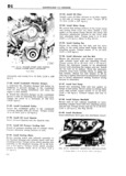
 Next
Next
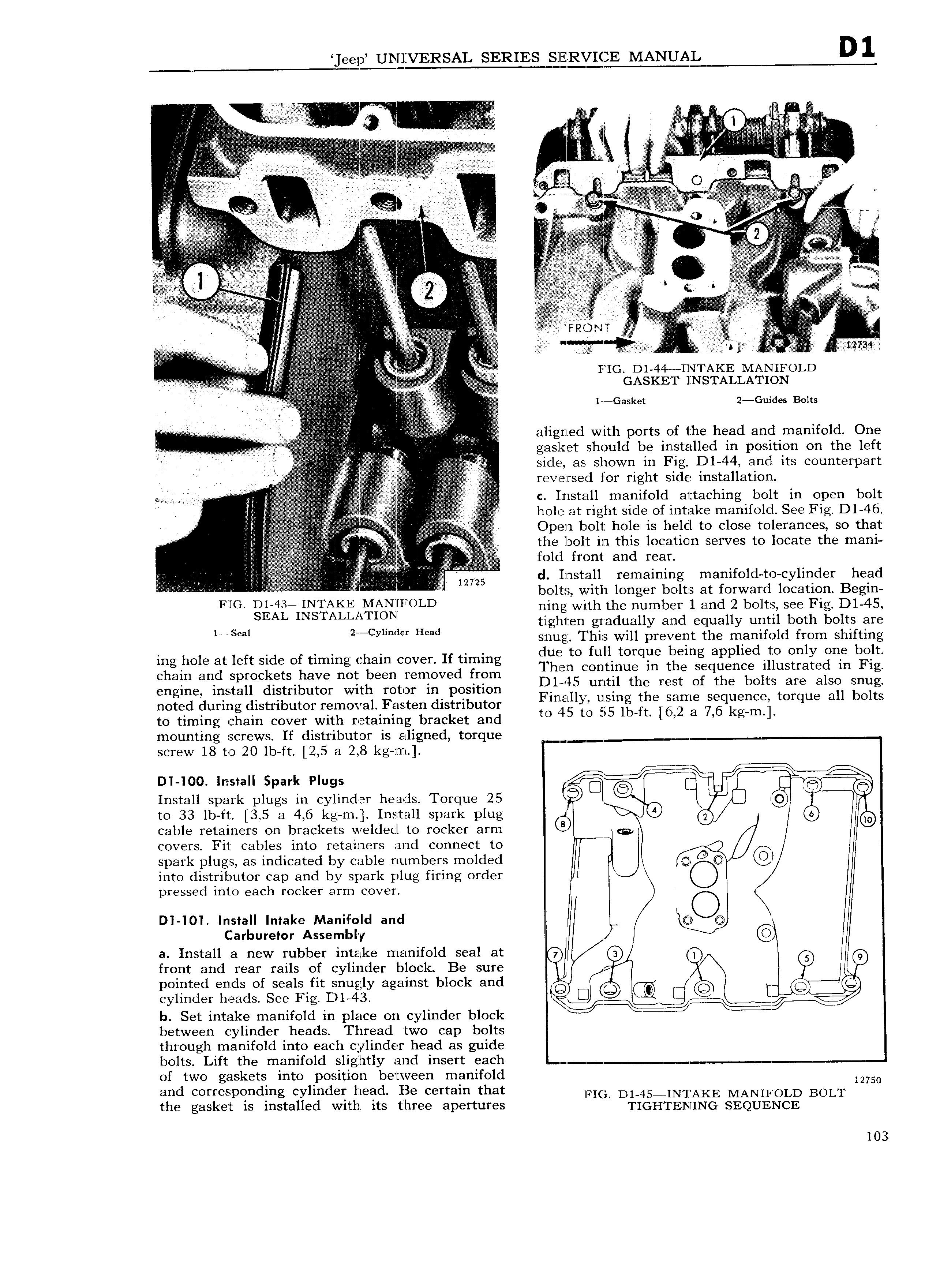
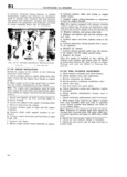
e ep UNIL ERSAL SERIES SZELRVIEIE MANUSQIL A E S S S S 2 Si S v Ei v S SS Q S s ASSSSS S i S 2 V V V V k A rr I O l F i A S S S2 S V s E E z Ez V z S ii V S r SS Si s J S S S Si J S to S S Q V 4 i S S S S S S LS T S AS S S S E SS S S J S v v Sv v L v z all l 5 21 I S 3 J S S V V 5 V V z V 1 4 tg i E v S S V K V vzz Ez Itg S S vE 1 S SSS v 4 AV S S SSS i tg S A S V f i Q 2S S SSE I S Si S SS S S S S SSS En S I SSS SSSSS FSR i T S S S SSS S SS v S V S SSSSSS A S me S S S i 5 V vS i S SS S S S S SS S S SS S S SSSS S V vr V 5 V S S rio D1 44 INTAKE MAN1 roLD SSSS S SSSS S S v v SS GASKET INSTALLATION SS S S SSSS S SS SSSS SSSSS Tg SS Q SS r c aska 2 Guides Bolts L S 2 SVS SSSSSV S I S S S S i S A VSS S Q S SSS s v VES aligned with ports oi the head and manifold One SSSSSS S SS S S S S l S SS S V SSS SS aslret should be installed in position on the left 2 i T 4 4 S S side as shown in Fig D 1 44 and its counterpart S g reversed for ri ht side installation S S 2 V S 1 S a S g iyxk V L S H S S T c 1 lStZ lll manifold zi1tta Chl g bolt lil Op H bolt S S S SSSS S l hole at right side of intake manifold See Fig D 1 46 S SiS iS i iS S S i I 1 S EV Open bolt hole is held to close tolerances so that S V S tlS1e bolt in this location serves to locate the mani S S S SI i fold fwnlt amd fem S V QSQSS SSSSSS SS SS d Iinstall remaining manifold to cylinder head S SS S S SSSS S S SS S SS SS S S S bolts with longer bolts at forward location Begin F lG ll l I FOLD ning witl1 the number 1 and 2 bolts see Fig D1 45 V V tighten gradually and equally until both bolts are 1 S l 2S y1 d Head snug This will prevent the manifold from shifting ing hole at left side of timing chain cover If timing dlm to fun torqlle bmng apphedrco Only 01 6 b lt lhen continue 1n the sequence illustrated in Pig chain and sprockets have not been removed from D145 t l th Qt f th b It Y I n engine install distributor with rotor in position F H unl ti mj O ES O Sta 8 3 S noted during distributor removal Fasten distributor i ft Q glgme qE nC Ofque 3 0 S to timing chain cover with retaining bracket and tg S O S S 3 g m mounting screws If distributor is aligned torque screw 18 to 20 lb ft 2 5 a 2 8 kg rn EEEEE E DI IO0 Install Spark Plugs X J 6 3 Install spark plugs in cylinder heads Torque 25 T T 19 S to 33 lb ft 3 5 a 4 6 kg rn Install spark plug 4 Q S60 cable retainers on brackets welded to rocker arm E covers Fit cables into retainers and connect to SS spark plugs as indicated by cable numbers molded gt Q into distributor cap and by spark plug firing order pressed into each rocker arm cover DI lOl Install Intake Maniliold and S C Carburetor Assembly l A T a Install a new rubber intake manifold seal at Q 6 lg front and rear rails of cylinder block Be sure l K l pointed ends of seals fit snugly against block and iis cylinder heads See Fig D1 43 Ei d b Set intake manifold in place on cylinder block J between cylinder heads Thread Stwo cap bolts through manifold into each cylinder head as guide bolts Lift the manifold slightly and insert each i of two gaskets into position between manifold 12750 and corresponding cylinder head Be certain that FIG D 45 IN I AKE MANIFOLD BOLT the gasket is installed with its three apertures TIGHTENING SEQUENCE 103