Ford Parts Wiki | GM Parts Wiki
Home | Search | Browse
Prev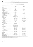
 Next
Next
44444444
444444
44444444
44444444
444444
444444
4444444
44444444
444444
4444444
444444
444444
44444444
44444444
eep UNIVERSAL SERIES SIDRVICE MANUAL D 1 l I D1 105 DHUNTLESS V 6 ENGINE SP lEZCI F ICHTIONS Cont1nued l English Metric CONNECTING RODS l Material 4 4 4 Pearlitic Malleahle Iron 4 4 Installation 4 4 4 From Top of Cyliricler Bore l 4 4 Bearings l Type 4 Removable Stee1 E3acked l 4 Material 4 V 4 4 l Aluminum 4 Length 4 t t 737 l 18 72 mm Clearance l 0020 to 002 3 4 0 0508 a 0 0584 mm End Play total for two connecting r ds l 006 to 014 0 153 a 0 356 mm4 CRANKSHAFT Material i I Pearlitic Malleable Iron i 4 End Thrust 4 Second Main Bearing l End Play t 4 4 l 004 to 008L 0 102 a 0 203 mm Main Bearings 1 Number 4 Type 4 4 l Removable 4 4 4 4 4 Material 4 4 4 l 4 Moraine 100 4 4 i Length Over All l No 1 No 3 and No 4 864 l 21 95 mm No 2 4 r 4 4 1 057 4 2 685 cm Clearance 4 4 y 0005 to 002 1 0 0127 a 0 0533 mm Main journal Diameter 4 4 i l 2 4995 6 349 cm Crankpin journal Diameter 4 l 2 0000 5 080 em Flywheel Run Out max r 4 015 l 0 381 cm CAMSHAFT Material i Cast Iron Alloy 4 4 4 Bearings l l Number 4444 4 4 Material 4 4 4 4 4 4 4 4 4 Steel Backed Babbitt 4 4 Clearance 4 4 4 4 l O015 to 0040 0 0381 a 0 1016 mrn4 journal Diameter N6 1 4 4 4 t 3 1 755 to 1 v1 s6 i 4 458 3 4 460 Cm No 2 4 4 4 4 4 4 1 725 to 1 71i i 4 382 a 4 384 cm NO 3 4 4 4 444 4 4 1 1 695 140 1 6 1 4 305 a 4 307 em No 4 4 4 4 i 1 665 to 1 666 4 229 a 4 231 ein Location 4 4 4 4 4 4 i In Cylinder Block at Center of V 4 4 4 4 4 Camshaft Drive 4 44 4 4 4 4 Chain and Sprocket 4 4 4 4 4 Chain Links 4 44 4 4 4 44 444 4 54 4 4 44 4 4 4 Camshaft Sprocket Material 44 4 4 4 4 4 Aluminum Nylon Coated 4 4 4 44 4 4 Crankshaft Sprocket Material 4444 4 4 4 4 4 Sintered 1 1 Tl 4 44 4 4 44 VALVE SYSTEM l Valve Lifters 4 444 4 4 4 444 4 4 4 4 4 4 V Hydraulic 4 444 4 4 Diameter 444 4 44444 4 4 4 4 4 44 4 44 8422 to 841Z 7 21 39 a 21 40 mm Clearance in Cylinder Block 4 44 4 4 4 4 4 4 0015 to 0 30 0 0381 a 0 0762 mm Leak down Time seconds 4 444 4 4 4 4 4 4 12 to 60 4444444444 Rocker Arms Ratio 444444 4 4444444444 4 44 44 4 14641 444444444444 Clearance on Shaft 4444 44444 4 4 4 4 4 0017 to 00 3i4Z 0 0432 a 0 0812 mm Valves l 1 Intake l l Material 4 4 44444 4 4 4 44 44 4 4 Steel SAE 1041 4 44 4 44 4 Head Diameter 44 4444 44 4 4 4 4 4 4 1 625 4 4 128 cm Seat Angle 44 44444 44 4 4444 4444 45 1 44444 4 4444 Stem Diameter 44 444444 4 4 4444 4 3415 to 342 7 8 674 a 8 704 mm Stem Clearance in Guide 4 444444 4 0O12 to 003 l2 4 4444444 Exhaust Material 4 444444444444 444 4 4 GM N82152 IZ1 4N 4 4 444 444 4 Head Diameter 4 4 4 44444 44 44444 1 3750 3 49245 cm Seat Angle 444444 4 44 44 4 44444 45 4444444 44 Stem Diameter 444444 4 4 4 44 444444 3402 to 341 2 8 641 a 8 666 mm 3397 to 3407 8 628 a 8 653 mm Stem Clearance in Guide 44 4444 44 0O1S to 003F top 1 0 0381 a 0 0889 rnm 002 to 004 bottom i 0 051 a 0 1 2 mm4 Valve Springs Pressure at Length Valve Closed 4 44444444 4444 444444444 14640 at 59 64111 4 16 cm at 26 76 29 03 kg 1 260 at 168 lb i 3 20 cm at4 76 20 kg 107