Ford Parts Wiki | GM Parts Wiki
Home | Search | Browse | Marketplace | Messages | FAQ | Guest
Prev

 Next
Next
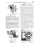
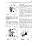
E FUEL SYSTEM There are six adjustments curb idle speed curb idle mixture Hoat level Hoat drop accelerator pump and fast idle This carburetor has six basic systems float low speed main metering power accelerator pump Azg and choke A E 26 Float System w The Hoat system controls fuel level in the car buretor fuel bowl It maintains constant fuel level to assure proper metering through all operating w ii ii ranges Fuel enters the carburetor through the inlet screen Il ll and inlet valve It Hows past the valve needle and 9 into the fuel bowl Fuel continues to How until 0 increasing fuel level raises the Hoat to a position 0 in which it forces the inlet valve needle into its 2 l l l l l l seat This closes the inlet valve As fuel is used from the bowl the Hoat moves downward slightly 0 28 3 This allows the valve needle to move away from its FIG E 18 IDLE SYSTEM seat Thislagain allows fuel to enter the fuel bowl d Ai Bleed 6 Th Omc Valve to maintain fuel level In this manner float level 2 Idl Air B Si 7 Id N d1 H l 3 Idle Restriction 8 Adjustment Needles maintains fuel level constant See Fig E 17 4 Lower Idle Restriction 9 Main Metering Jets 5 Off Idle Discharge Port l0 Idle Tube A Throttle Valve in OH Idle Position In idle speed position each throttle valve is slightly open This allows a small amount of air to pass Im between the carburetor bore wall and the throttle 7f Q ij valve Since there is not enough air How for ven i 4 M turi action manifold vacuum draws fuel directly 9 5 j from the fuel bowl through the idle system Q L V Fuel from the Hoat bowl passes through each main V metering jet into the main well A metered amount l of fuel Hows through the idle tube restriction It then passes up the idle tube to a passage where it is mixed with air drawn through two calibrated idle air bleeds Fuel air mixture then Hows through a calibrated restriction into a vertical passage It 1 passes through another calibrated restriction to 0 Q Q Q the off idle discharge slot just above each throttle valve This injects additional air It then Hows through the idle discharge port The idle mixture 12838 needle controls the amount of fuel air mixture FIG E 17 FLOAT SYSTEM which enters the carburetor bore at curb idle posi 1 Internal Bowl Vent 4 Float Tang tion Of the throttle valve 2 Fl0 t 5 F1oat Needle As the throttle valve opens farther more and more 3 N dl Pull Chp 6 N cdl Seat of the off idle discharge slot is exposed to manifold A Hoat prong at the rear of the Hoat arm between Eifsiflgnlaqggiciiggggizugg iiii gg r E l an mix the Hoat hangers prevents the Hoat from moving too far downward yet allows it to move downward E 28 M ain M etering System far enough to allow maximum fuel How into the b0wl April ein connects the neat arrnte rneveive AS the theme valve S to its edge needle This keeps the needle from sticking in the lsgglliiiSalvgguiigglgpglii ligbilgit 51 b3 C1l PS3 scat because Of dirt Or gum formation and off idle discharge slot so that the idle system E 27 dl S t ceases to supply fuel air mixture 9 YS em With increased throttle opening air velocity During engine idle operation air How through the through the venturi increases This causes a de carburetor venturi is very low It is insufficient to crease of pressure in the carburetor bore which is cause fuel to How from the main discharge nozzles multiplied in the venturi See Fig E l9 Therefore theidle system supplies fuel air mixture Since the low air pressure vacuum is in the during idle and low speed operation venturi at this time fuel Hows as follows The idle system consists of the idle tubes idle pas Fuel from the Hoat bowl passes through the main sages idle air bleeds idle mixture adjustment metering jets into the main well and rises into needles off idle discharge slots and idle discharge the main well tubes Air enters the main well ports See Fig E 18 through the main well air bleeds and mixes with 120

 Next
Next