Ford Parts Wiki | GM Parts Wiki
Home | Search | Browse | Marketplace | Messages | FAQ | Guest
Prev

 Next
Next
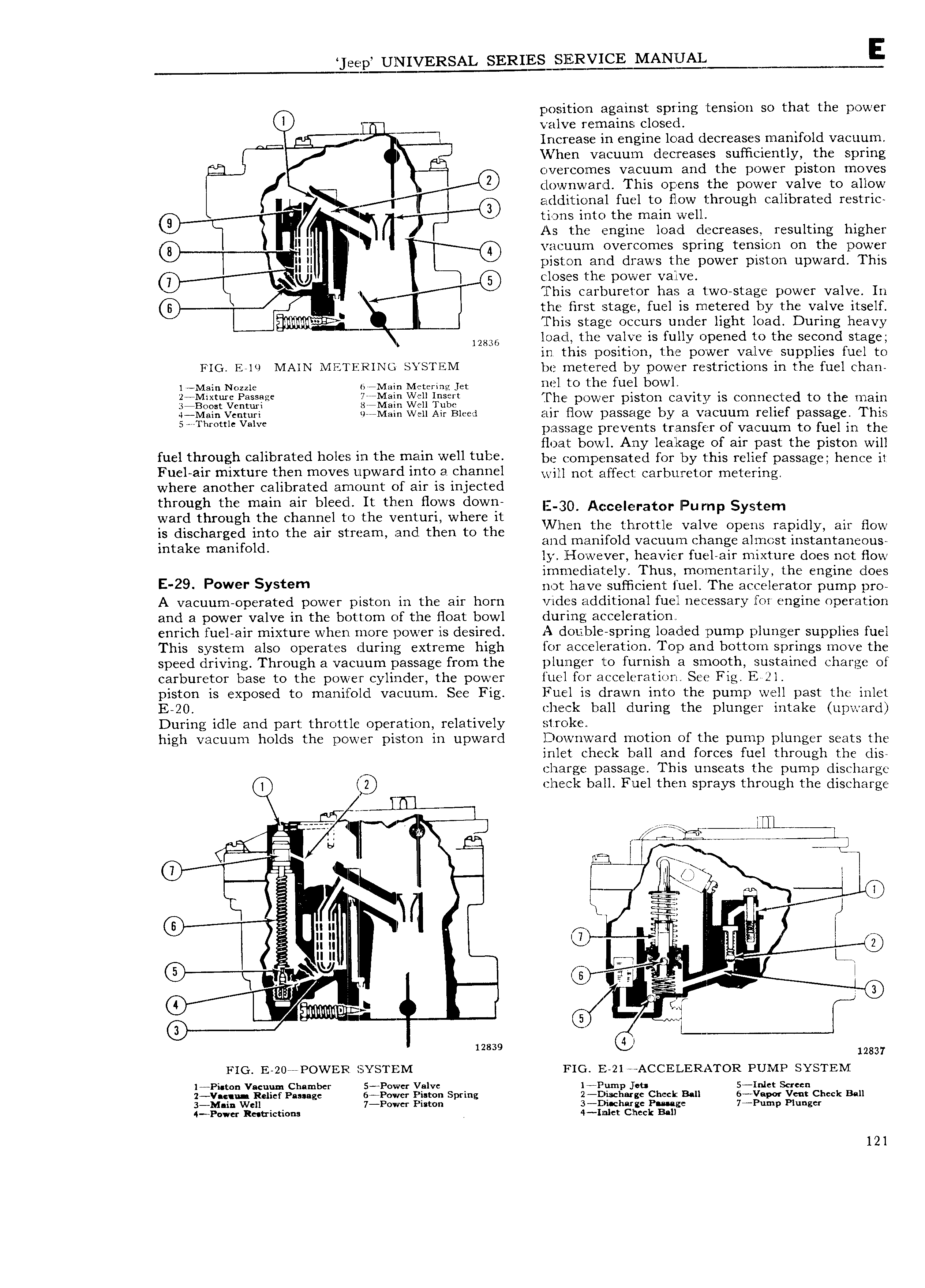
eep UNIVERSAL SERIQEi l ByICE MANQE E position against spring tension so that the power valve remains closed jj Increase in engine load decreases manifold vacuum Vl hen vacuum decreases sufficiently the spring Xi overcornes vacuum and the power piston moves downward This opens the power valve to allow A E additional fuel to flow through calibrated restric 9 Y ix tions into the main well As the engine load decreases resulting higher ll W vacuum overcomes spring tension on the power H W piston End draws the power piston upward This 7 Ky closes t e power valve 4 This carburetor has a two stage power valve In the first stage fuel is metered by the valve itself L This stage occurs under light load During heavy loacl the valve is fullv opened to the second stage s 12836 I in this position the power valve supplies fuel to FIG E l 9 MAlN Ml l PZRlNG SYSTEM be rneteijred by power restrictions in the fuel chan l Main Nozzle r Main Metering jet ncl to it K fuel bOVV1 cj c jj gjjxg f The power piston cavity is conneeted to the main l Main Venturi W Main Well Air Bleed Eur Elow p3SSE1g by 3 VHCULIITI 1 lI f passage This 5 I hr0ttlc Valve i passage prevents transfer of vacuum to fuel in the g H V r e float bowl Any lealrage of air upast the piston will fuel through calibrated holes llfl the Hlelm well U 1l3 be compensated for by this relief passage hence it Fuel air mixture then moves upward into a channel evil net eggeeg eerbweter metering where another calibrated amount of air is injected through the main air bleecl It then flows down E 3O Akccelegratm Pu mp System ward through the channel to the venturi where It VW th tb ttl I is discharged into the air stream and then to the km no B V3 VC OPENS m91dly an HOW intake m mgi Old and manifold vacuum change almost instantaneous ly ll low ever heavier fuel air mixture does not flow immediately Thus momentarily the engine does E 29 F wer Y t9m not have sufficient fuel The accelerator pump pro A vacuum operated power piston in the air horn vides additional fuel necessary for engine operation and a power valve in the bottom of the float bowl during acceleration enrich fuel air mixture when more power is desired A double spring loaded pump plunger supplies fuel This system also operates during extreme high for acczeleration Top and bottom springs move the speed driving Through a vacuum passage from the plunger to furnish a smooth sustained charge of carburetor base to the power cylinder the power fuel for acceleration See Fig 2l gsggn is exposed to manifold vacuum See Fig liuelkis drawn into the pump well past the inlet c rec ball during the plunger intake upward During idle and part throttle operation relatively stroke high vacuum holds the power piston in upward Downward motion of the pump plunger seats the inlet check ball and forces fuel through the dis charge passage This unseats the pump discharge 3 check ball Fuel then sprays through the discharge IlIl Z A I 3 I Z7 e 7 t Llill 5 ei iE e e i l e it 1 U l z es l X5 We 5 jr Q vw 1 F gra l ZE 0 gg gg l e I 2 n u l ISU I mt e u u s 1 use 0 L g tial 3 l sa F g C I izaas Q5 12837 FIG E 20 POWER sYsTI M FIG E 21 ACCE1L ER ATOR PUMP SYSTEMZ l Pi ton Vacuum Chamber S P0wcr Valve l Pump jet 5 Inlct Screen 2 Vaa u Relief Passage 6 Power Piston Spring 2 Discharge Check Ball 6 Vapor Vent Check Ball 3 ll rVll E icti ns 7 P0wcr Piston rgc llsagzaggie 7 Pump Plunge V C CC l2l

 Next
Next