Ford Parts Wiki | GM Parts Wiki
Home | Search | Browse
Prev

 Next
Next
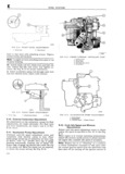
eep UNIVERSAL SERIES MANQEL m E exterior moving parts of a carburetor are often c lnstall two main metering jets power valve responsible for unsatisfactory performance For this gasket and power valve Y 3 0n ciiicient Cafbumtinln d P nds UlPOn Canitnl d Install small aluminum inlet check ball in ac cleaning and ln D ti0n while 5 rvi i g ce erator pump inlet at bottom of pump well ln a Thoroughly clean carburetor castings and metal sert pump return spring into well and center by parts in carburetor cleaning solvent pressing spring downward with finger Caution Accelerator pump plunger and any nber S ltistall pump inlet screen in bottom of fuel or rubber parts should never be immersed in car OW buretor cleaner Wash pump plunger in cleaning solvent m m t E 39 A H El rd bl b Blow out all passages in the castings with com I 0 lstty isgemu y F Y k 1 fj DT d all Dry all parts with compressed any nstaj gnk dll Offai nYc lofe ia Make sure all jets and passages are clean Do htsflii 3 C L3 it mu hdl talk mm as not use wire to clean fuel passages or air bleeds ml t fy am C l Op O C O ti Up EVE C check mia valve miie md Sat ra War rr P S a l Sl gt l r lcv egjrgbgv mm ih wear is noted the assembly must be repla ced an ism O ti m mt m t C O C CVC must face fuel inlet side ol carburetor d Check float hinge pin for wear and check float C I mu hOk Vine Nate hg k h ft SC that f d 1S C Yi il incoesg Or Cimigih ttl d h ka Uh ft b f letters RP will face upward in nnished carburetor Eid C f to dt an C O L Q 3 ONES Or Wear ITn t all tWO U fW Val plate attaching screws but an Ou O jmun do not tighten securely until valve plate is centered f Inspect idle mixture adjustment needles for burrs To mntcr ChC k vajlvc plate OH Choke shaft hold OT gI OOV replace if d3mZig ECl chcike valve tightly ClO 2d tholl slide choke shaft g Inspect cup of accelerator pump plunger re inward to obtain approximately 020 0 508 mm place if darr aged worn or hardened Inspect pump clearance between choke trip lever and choke lever well in bowl for wear or scoring ar d collar assembly Tighten choke valve screws h Check nlter screens for clirt or lint Clean and iT l1T lIV and tak l gh ly in Pl3 Chvke valve if they remain dogged ycp a Cc will belperfectly free in all positions when installed i If for any reason parts have become loose or Cgmsctiyt damaged in thg Cluster as g ynb yl the assembly d II lS Ii lZOL1t I 3C Z lETI 3lZ I pl 1l 1 Ipl VCI HI1dSl lElft3S must be y p aC d semloly into air horn body with lever pointing to warcl choke shaft Install inner pump arm with Ntgai Ussbasgv gaskets Wnanavct thc rb r t r plunger hole inward and tighten set screw securely is lsassam E Position pump plunger assembly on inner pump arm with pump shaft pointing inward and install retainer E 37 Th tt B dY A m b Y e Install needle seat screen on inlet valve seat In a Install idle mixture adjustment needles and stall seat and gasket in air horn body Tighten seat springs in throttle body Tighten finger tight then securely with a wide blade screwdriver nntntcad Ont tum as a P nminatY ad i Stm t f Install power piston into vacuum cavity Lightly setting stake piston retainer washer in place Piston should Caution Do not force idle mixture adjustment ttaivtil fatal m caV tY needles against seats or damage may result g Install air horn gasket on air horn body fitting T g T gasket over guide pin weft ue OW O y mi pine new t mttc h Attach inlet valve needle to noat Carefully body gasket on bowl Fasten throttle body to bowl bod with three Screws and lOCkWaS rS ti htcn position float and insert float hinge pin Drop tang sccuxely g at rear of float arm downward toward air horn i i llristsall fuel inlet fitting if removed j With air horn assembly inverted measure the E 38 Fuel Bowl B0dY A fFF mblY distance from the air horn gasket to top of Hoat ll r a Drop steel discharge check ball of accelerator at tas l i7 7t nm l tat standard tfatbnnatnts pump into discharge hole llnstall pump discharge ann 1 32 l29 36 nnnzl tat exhaust smgssron tr l spring and rlgshapcd f mim T Stake retainer in equipped carburetoifi ag shown in Fig E 2o Use placa float level gauge f l2 2 Bend float arm as re Q 1l f d 4 adjust 10 1 l43v5l N t TOP Of tetamet must be Hush Wlth Hat k Vllith air horn body held upright measure dis surface ff 1b w1b dy tance from gasket to bottom of float pontoon at b Install two inserts in main well Align surface slut tl t d Usa a l 47 62t mnt Esate drop on lip of insert with flat surface in recess on top a s L E 1H tmt g as Y Qnn d tn ndlusl float of main well Install venturi cluster with gasket Cntll Flg E 4 and tighten mounting screws evenly and securely I Carefully place air horn body on fuel bowl Be certain that center screw is fitted with fiber body making certain that thelaccelerator pump gasket and that a special smooth shank screw is plunger is properly positioned in the pump well used Lower the cover gently straight down install air 123

 Next
Next