Ford Parts Wiki | GM Parts Wiki
Home | Search | Browse
Prev

 Next
Next
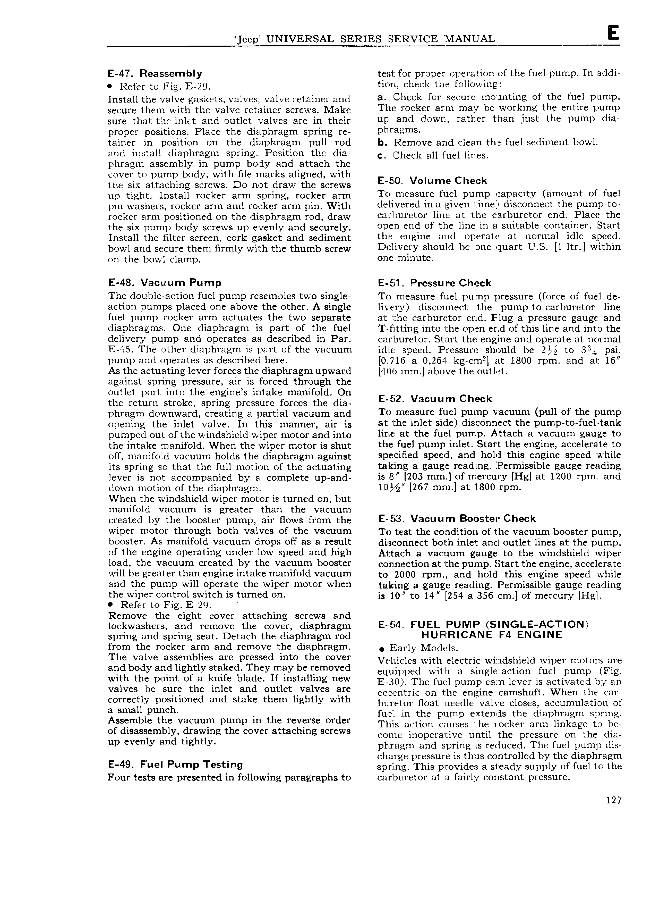
ljeepl UNIVERSAL SERIES SERVICE jMANUAL E E 47 Reassembly test for proper operation of the fuel pump In addi Refer to Fig E 29 tion check the following Install the valve gaskets valves valve retainer and 6 Chcclii tct sccutc mtluntlng of thc fuel Plump secure them with the valve retainer screws Make The l70ck l arm may be Wctklng thc cntltc Pump sure that the inlet and outlet valves are in their unl and clOWn rather than Just the Pump Cha proper positions Place the diaphragm spring re Phtagms tainer in position on the diaphragm pull rod b Remove and clean the fuel sediment bowl and install diaphragm spring Position the dia c Cphcckauf u 1 i E S phragm assembly in pump body and attach the cover to ump bod with file marks aligned with the six agtaching sgrews Do not draw the screws E 5 O Vlllume Check n up tight Install rocker arm spring rocker atm To measure fuel pump capacity amount of fuel pm washers rocker arm and rocker arm pin With d 5 llV cl d iu a eiveu tlmcil chsccnncct the PumP tc rocker arm positioned on the diaphragin rod draw cairbunretor line at the carburetor end Place the fhg six punjp scfcwg up evenly and Sccuyc1y O I Cllld of tI1 lll1C lll 13 SL1lt3blC COIIYZGIIICI iSt3I t Install the filter screen cork gasket and sediment thc cosine aud Opctatic at normal idle slPccd bowl and secure them firmly with the thumb screw Delivery should be unc quart US ll ltt l witliiu on the bowl clamp cnc mlnutc E 48 Vacuum Pump E 51 Pressure Check The double action fuel pump resembles two single To measure fuel pump pressure force of fuel de action pumps placed one above the other A single livery disconnect the pump to carburetor line fuel pump rocker arm actuates the two separate at the carburetor end Plug a pressure gauge and diaphragms One diaphragm is part of the fuel I fitting into the open end of this line and into the delivery pump and operates as described in Par carburetor Start the engine and operate at normal E 45 The other diaphragm is part of the vacuum idle speed Pressure should be to 3 psi pump and operates as described here 0 716 a 0 264 kg cm2 at 1800 rpm and at 16 As the actuating lever forces the diaphragm upward 406 mm above the outlet against spring pressure air is forced through the outlet port into the en ine a intake manifold On the return stroke spririg pressure forces the dia Er 5 r llllnuum C k phragm downward creating a partial vacuum and To mcelsutc fuel Pump vacuum Duh of thc Pump Opening hg inlgt Vg v In this ynanngy air is at1 he lI 1l 3t side dlSCOH1 lCCt thC pl1Il 1p lCO fl1Cl t8Dl pumped out ofthe windshield wiper motor and into hnc at the fuel Pump A ttach a Vacuum gauge to the intake manifold When the wiper motor is shut thc lfucll Pump inlet Staift the eueiriev accelerate to otf manifold vacuum holds the diaphragm against Slsccllhcd speed arid hold this engine speed while its spring so that the full motion of the actuating taking a gauge readfiiig Permissible gauge reading lever is not accompanied by a complete up and is 8V 2 ssmm 1 f mfifcufy Hel at 1200 YPm and down motion of the diaphragm 10 W l267 mm l at il 800 tPm When the windshield wiper motor is turned on but manifold vacuum is greater than the vacuum created by the booster pump air Hows from the EZ 53 Vacuum B i St Chcck wiper motor through both valves of the vacuum To test the condition ofthe vacuum booster pump booster As manifold vacuum drops off as a result disconnect both inlet and outlet lines at the pump of thc engine operating undef l0W speed and high A 1 t ach a vacuum gauge to the windshield wiper load the vacuum Cfcatcd by the Vacuum booster C DH l EClZi lfl at the pump Start the engine accelerate will be greater than engine intake manifold vacuum to 2000 l pm and hold this engine speed while aud thc Pump will operate the wiper motor when taking a gauge readirig Permissible gauge reading the wiper control switch is tu rned on is 10 130 14 254 a 356 cm of mercury Hg Refer to Fig E 29 Remove the ei ht cover attachin screws and lockwashers ang remove the covgr diaphragm Ev 5 l FUEL PUMP lNGLE ACT ION spring and spring seat Detach the diaphragm rod HUFlTRlC ANE F4 ENGINE from the rocker arm and remove the diaphragm Early ll lOd lS The Valve aSS mbll S are pmlsscd mee the Cover Vehicles with electric windshield wiper motors are alld body allfl llglltly St l l Tllley llllly be remeved equipped with a single action fuel pump Fig with the rmt ef e kmfe l le le If i te i e eW E 3o me fuel pump can lever is activated by an Valves be slll the llllet alllil Oullletwvallvcs lfllc eccentric on the engine camshaft When the car Colillcctly f Sltl d and sltglkli them llglltly Wltll buretor float rieedleivalve closes accumulation of El Smell punch fuel in the pump extends the diaphragm spring Assemble the Vacuum pump ln the mvflsc Ol dcr This action causes the rocker arm linkage to be of disassembly drawing the cover attaching screws wm m0 p ra iV until the pressure On the dia up cvcnly and tlghtly phragm and spring is reduced The fuel pump dis charge pressure is thus controlled by the diaphragm E 49 Fuel PumP Tc tl l9 spring This provides a steady supply of fuel to the Four tests are presented in following paragraphs to carburetor at a fairly constant pressure 127

 Next
Next