Ford Parts Wiki | GM Parts Wiki
Home | Search | Browse
Prev

 Next
Next
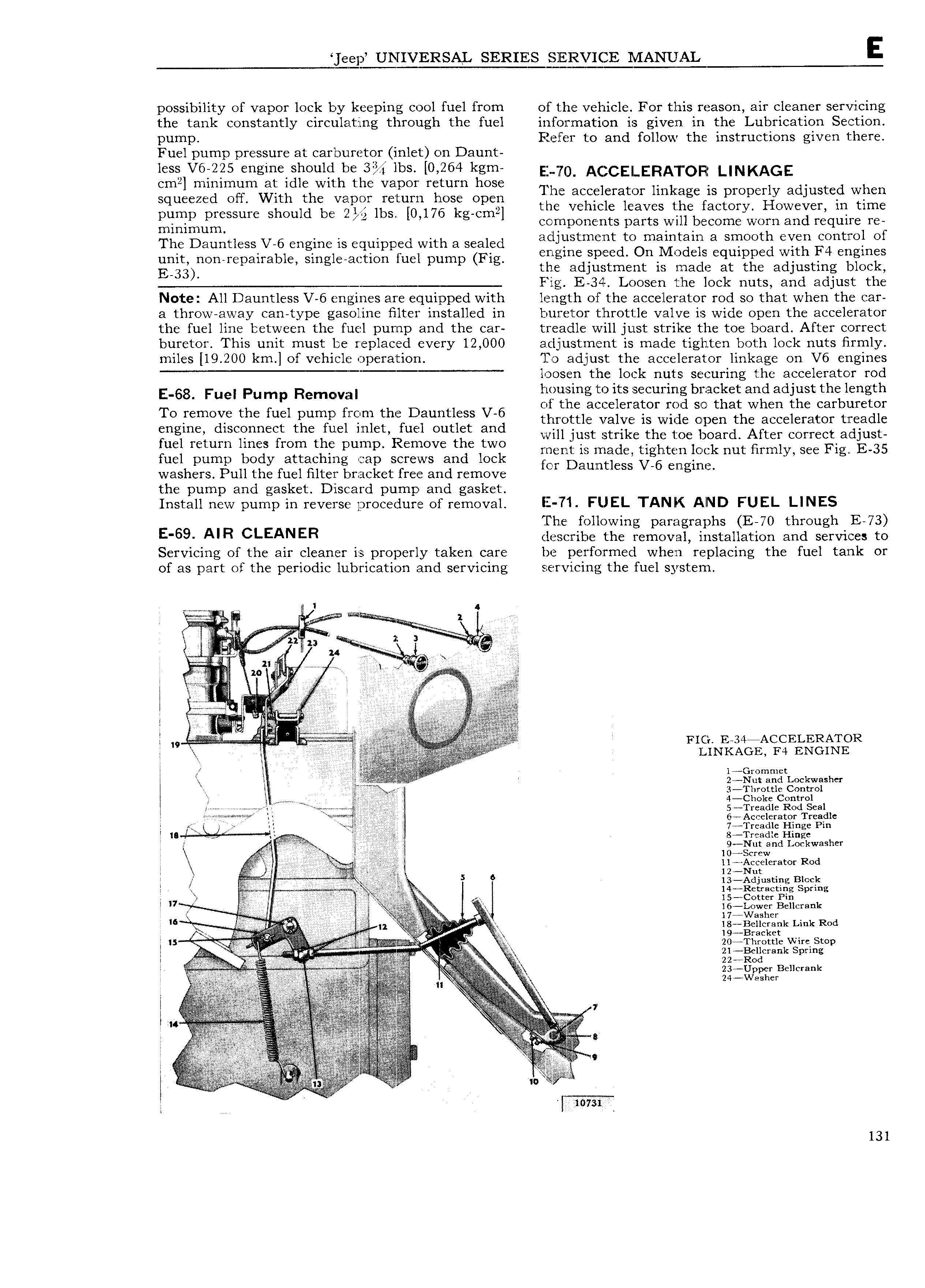
ee UNIVERSAL SERIES SERVICE MANUAL E possibility of vapor lock by keeping cool fuel from of the vehicle For this reason air cleaner servicing the tank constantly circulating through the fuel information is given in the Lubrication Section pump Refer to and follow the instructions given there Fuel pump pressure at carburetor inlet on Daunt less V6i225 engmelshould he lbs 0 264 kgm E 0 4Ac CE LERATOR LINKAGE cmg mmlmum at Idle Wlth the Vapml mmm hose The accelerator linka is ro erl ad usted when squeezed off With the vapor return hose open the Vchil 1 tjilgcfa grp Higweg er in time pump pressure should be 2 lbs 0 176 kg cm 1C eaves 1 Q C y minimum components parts will become worn and require re The Dauntless V 6 engine is equipped with a sealed 3djrllstrmi ntdt bm bF t 1 3 SWOMS Y 1T ZntmlnOf unit non repairable single action fuel pump Fig engine SPEC H O S Gqmppe Wl Engl es E 33 the adjustment is made at the adjusting block Fig E 34 Loosen the lock nuts and adjust the Note All Dauntless V 6 engines are equipped with length of the accelerator rod so that when the car a throw away can type gasoline filter installed in buretor throttle valve is wide open the accelerator the fuel line between the fuel pump and the car treadle will just strike the toe board After correct buretor This unit must be replaced every 12 000 adjustment is made tighten both lock nuts firmly miles 19 200 km of vehicle operation To adjust the accelerator linkage on V6 engines loosen the lock nuts securing the accelerator rod E 68 Fuei pump Removal housing to its securing bracket and adjust the length TO remove the fuel um fmm th Dauntlcss V 6 of the accelerator rod so that when the carburetor p p throttle valve is wide open the accelerator treadle iniinek discpnneirt thctliucl 1Tg IgU l Outgit ind vvjll juggt gtyikg the toe board After COY1 C adjust ue rc urn mes mm fi pw p Gmovc C WO ment is made tighten lock nut firmly see Fig E 35 fuel pump body attaching cap screws and lock fm Daumlcss V 6 Cn mp washers Pull the fuel filter bracket free and remove l g the pump and gasket Dilsczard pump and gasket j Install new pump in reverse procedure of removal L 71 FUEL TANK AIND FUEL LINES The following paragraphs E 70 through E 73 E 69 AIR CLEANER describe the removal installation and services to Servicin of the air cleaner is ro nerl taken care be performed when re lacin the fuel tank or g P 1 Y P g of as part of the periodic lubrication and servicing servmcizng the fuel system www 1 4 m I 2 xs j Egg u V j F2 11 F E A i l E k I W l W WW FIG E 34 ACCELERATOR V r MNKAGE F4 ENGINE A r 14Gr r l AX A 2 Nut and Lockwashcr l Z gi w g 3 Throttl iCont ol 2 r c1 k t I M a mj y i l TQ a i 1 i f Y t r 6 Accelerator Treadle f H li Emir N 7 Trcadle Hinge Pin la 8 Treadle Hinge S M 9 Nut and Lockwasher V V r ff I 104 Screw Z g gfflerator Rod 5 6 1 B k E S Z jiigggxgglg g sgiing I I irl r o t 6 x r B m A rt lgiB i cZ k Link Rod I 1 l9 Bracket is 1 v j M 2 4Th 1 W E g f k SEi g r v o 23 Ugp r B r k tt rr Eioti W l 1 l 1l I r 5 I I i l 131

 Next
Next