Ford Parts Wiki | GM Parts Wiki
Home | Search | Browse
Prev

 Next
Next
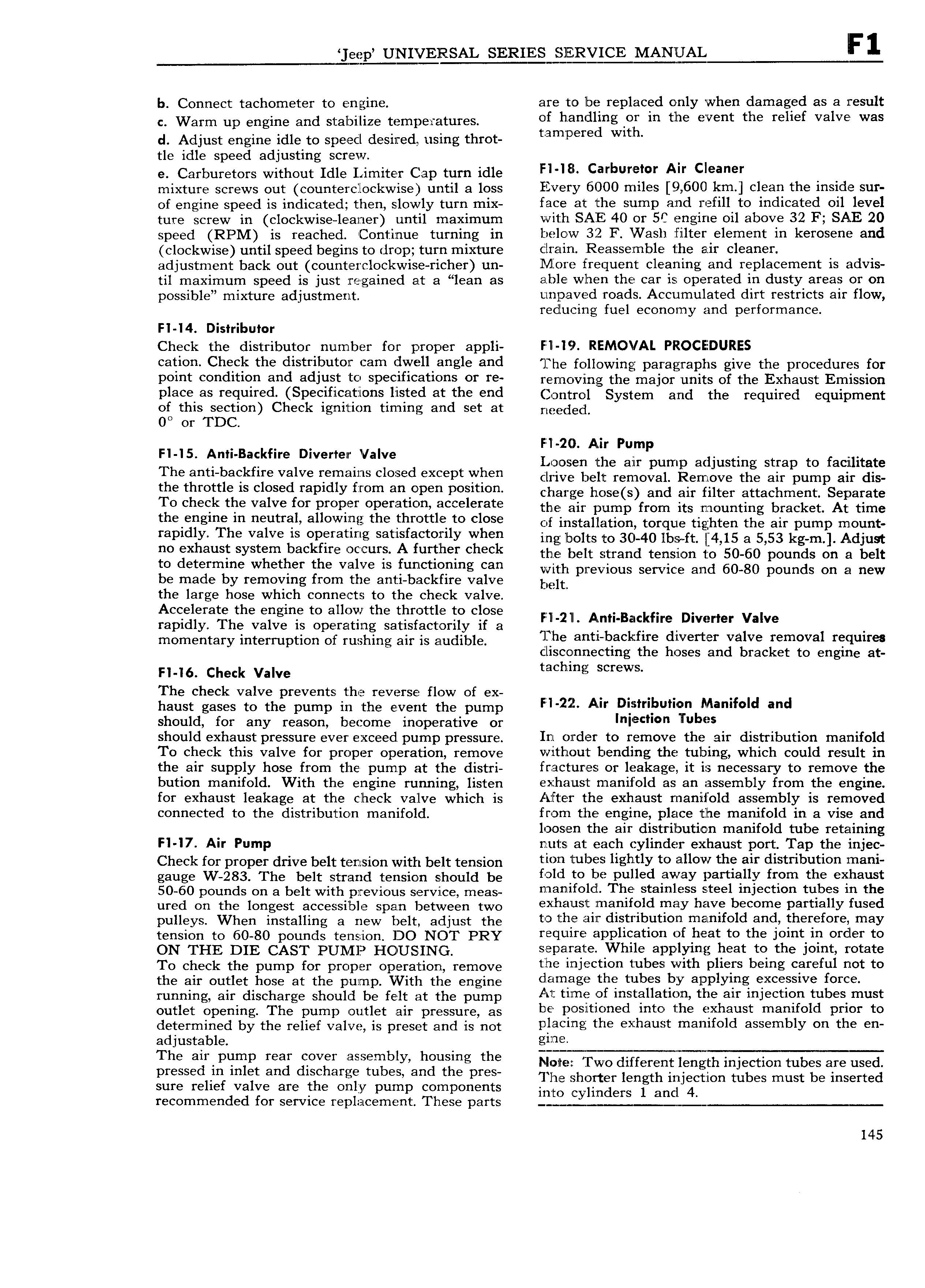
eep UNIVERSAL SERIES SEEYICE MANE b Connect tachometer to engine are to be replaced only when damaged as a result e Warm up engine and staluilize tempei atutes of handling lor in the event the relief valve was d Adjust engine idle to speed desired using throt t am p r d with tle idle speed adjusting screw e Carburetors without Idle Limiter Cap turn idle Fl l8 c rbu l r A Cleaner mixture screws out counterclockwise until a loss Every 6000 miles 9 600 km clean the inside sur of engine speed is indicated then slowly turn mix face at the sump and refill to indicated 011 level ture screw in clockwise leaner until maximum with SAE 40 or SC engine oil above 32 F SAE 20 speed RPM is reached Continue turning in below 32 F Vi ash filter element in kerosene and clockwise until speed begins to drop turn mixture drain Reassemble the air cleaner I adjustment back out counterclockwise richer un More frequent cleaning and replacement is advis til maximum speed is just regained at a lean as able when the car is operated in dusty areas or on possible mixture adjustment unpaved roads Accumulated dirt restricts air flow reducing fuel economy and performance FI I4 Distributor Check the distributor number for proper appli Fill IS REMOVAL PROCEDURES 3tl0 Check this dlStYibUtOll Cam dwftll allgl 8l ld The following paragraphs give the procedures for paint abudititm aud adjust tb specificatibus ar re removing the major units of the Exhaust Emission place 8S I qL1lI Cl Sp ClflC2EltZiOI 1S listed at tl 1 Cfld Clgntrgl System and the required equiprnerlf of this section Check ignition timing and set at nppd d OO or TDC Fl 20 Air Pum H 5 Ami BackHre Diva fe Valve Loosen the air Fpump adjusting strap to facilitate The anti backfire valve remains closed except when cli ive belt removal Remove the aii pump aii dis the throttle is closed rapidly from an open P0 ltl0 Charge h ose s and air filter attachment Separate To check the valve for proper operation accelerate tlle aii pump from its mounting btacket At time thefmgme m utY lv allowmiii the thtettle ta elase of installation torque tighten the air pump mount rapidly The valve is operating satisfactorily when ing lnolts to 30 40 lbp fr 4 15 a 53 kg m Adjust H0 exhaust system haalsfue etuts A further eheak uio belt strand tension to sooo pounds oo ri belt to determine whether the valve is functioning can with ptevious service and o0 80 pounds on a new be made by removing from the anti backfire valve pelti the large hose which connects to the check valve Accelerate the engine to allow the throttle to close l rapidly The valve is operating satisfactorily if a Film Afn B Icj f e Dwtmer valve rriorriorirory interruption oi rushing air is audible llhe at t l lllzaalatue gi tlB gallye ltemayal tequues cisconnec mg e oses an rac e o engine a ri 16 chock Valve h g S S The check valve prevents the reverse flow of ex i l haust gases to the pump in the event the pump F l 2 i A D l P l Mamfald aud should for any reason become inoperative or I l ll b should exhaust pressure ever e xeeed pump pressure In order to remove the air distribution manifold To check this valve for proper operation remove without bending the tubing which could result in the air supply hose from the pump at the distri fractures or leakage it is necessary to remove the bution manifold With the engine rurming listen Xl l 1 L1S E manifold as an assembly from the engine for exhaust leakage at the check vaflve which is After the exhaust manifold assembly is removed connected to the distribution manifold from the engine place tlhe manifold in a vise and loosen the air distribution manifold tube retaining Fl I7 Air Pump nuts at each cylinder exhaust port Tap the injec ciiooir for proper drive belt tprisiou with belt tension tluh tubes lightly ta allaw the alt tllsttibutiau mam gauge w 283 The belt strarid torrsiori should be f alu t be pulled away vartlally tram the exhaust 50 60 pounds on a belt with pitevious service meas manifold The stainless steel injection tubes in the utcd on the longest accessible span between tvvo iLl lEllL1Sli lFI18I 11fOld may have become partially fused pu1l yS When installing a new belt adjust the tothe air distriblution manifold and therefore may tcnsion to 60 30 pounds tens ion DO N T PRY require application of heat to the joint in orcler to QN THE DTE CAST pUMl Hg USlNG separate While applying heat to the joint rotate To chock thc pump for propel opera tion remove the injection tubes with pliers being careful not to the air outlet hose at the pump with tho engine tlamase the tubes by aiaplyms exeesslye fatte funning air discharge should be felt at the pump Alf time of 1USU 1ll8t1 l I 1 the air injection tubes must outlct opening The puinp Ourtlet an pressure as be positioned into the exhaust manifold prior to determined by tho roiioi valve is preset arid is riot plasma the exhaust mamfald assembly ah the eu adjustable gl fl The a l F ml rear QOVEY as semhly hmlsmg the Nolte Two different length injection tubes are used pressed m mlet and dlsshatae tubes and the pres The shorter length injection tubes must be inserted sure relief valve are the only pump components inte Cylinders l and 4 recommended for service replacement These parts Q Q 145

 Next
Next