Ford Parts Wiki | GM Parts Wiki
Home | Search | Browse
Prev

 Next
Next
9115012
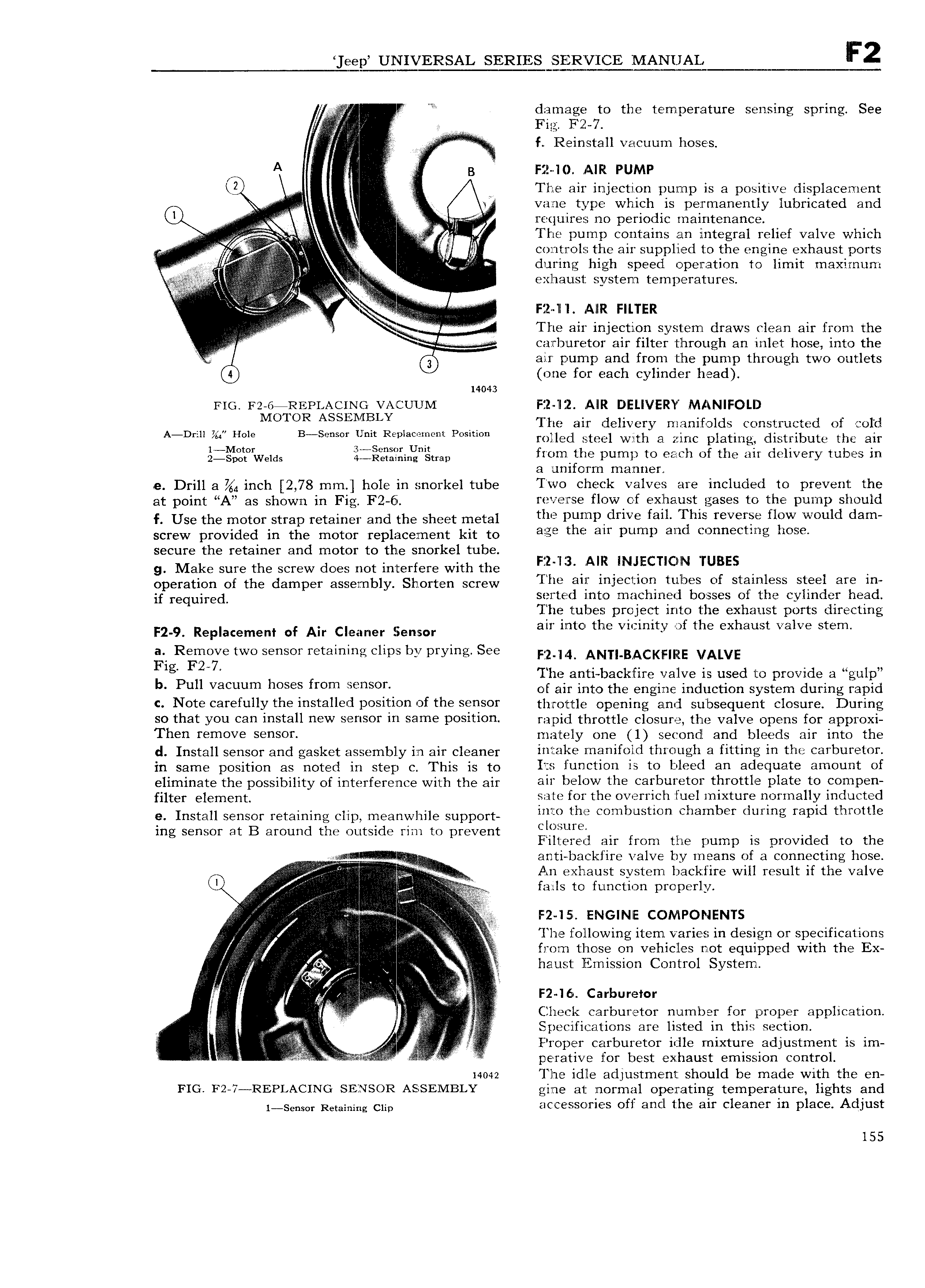
ee J UNIVERSAL SERIES SERVICE IVIANUAL T i ZIV V damage Pto the temperature sensing spring See E i Fla V V V X v IY E f Reinstall vacuum hoses A if I B F12 I 1 AIR Pump K2 V W The air injection pump is a positive displacement Pg i vane type which is permanently lubricated and ii V i 1 requires no periodic maintenance U I 4 A i i The pump contains an integral relief valve which i V r 1 cozntrols the air supplied to the engine exhaustiports i i V iii during high speed operation to limit maximum Vi r exhaust system temperatures l I l i in l i iiV r r l r l F2 ll I AIIR FILTER L v i l i I The air injection system draws clean air from the i 4 catrburetor a1r filter through an inlet hose into the g 6 air pump and from the pump through two outlets one for each cylinder head 14043 rio r2 6aRE1 1 Ac1No vacuum Fizi liz AIR DELIVERY MANIFOLD 7 N MOTOR AS NF LY The air delivery manifolds constructed of cold A D e me B S S flm Rr m i PMDH mites mei with at are plating distribute the air D f W rds Qj Q iig ti iiii frorn he pump to each of the air delivery tubes in a uni ozrm manner o Drill 3 V inch 2 78 mm hole in snorkel tube Two check valves are included to revent the 64 s i p at point A as shown in Fig F2 6 re vetrzse flow of exhaust gases to the pump should USE the motor Strap retaiiiei and the Sheet metal the pumpidrive fail I h1s reverse flow would dam screw provided in the motor replacement kit to agi the mr pump aud Connectmg hOS secure the retainer and motor to the snorkel tube I I g Make sure the screw does not interfere with the F z I 3 QAIB N ECl C l IUBES Operation Or the damper asgembly Shorrim Screw The air injection tubes of stainless steel are in if required sorted into machined bosses of the cylinder head The tubes project into the exhaust ports directing F2 9i Replacement of Air Cleaner Semor air into the vicinity of the exhaust valve stem a Remove two sensor retaining clips by prying See F 2 M AN BACKF iiE VALVE lg 2 7 The anti backfire valve 1S used to rovide a ul b p ll h p g u Vacuum OSB mm nSOT of air into the engine induction system during rapid C N0 f 3F f UY the 1 f3U d DOSIUOU of the S S0Y throttle opening and subsequent closure During so that you can install new sensor in same position rapid throttle closure the valve opens for approxi Th 1 1 1 10V 9115012 mately one 1 second and bleeds air into the d Install sgnsgr and gasket is5 mb y ii air Cleaner lllljillf llllfltlgh 3 fitting ll l l C3I bUI l0I in same position as noted in stop c This is to Its function is to bleed an adequate amount of eliminate the possibility of interference with the air all b l i W thi 3Yb t0Y thY0ttl Dlatf to 0mP filtoy olomonp sate for the overrich fuel mixture normally inducted Q Install Sensor retaining Clip meanwhile SiippOi into the combustion chamber during rapid throttle ing sensor at B around the outside rim to prevent llii ur i i ii d i i th iieret air rom arie pump is provi et o e H V anti backfire valve by means of a connecting hose i ll i i An exhaust system backfire will result if the valve Q i foils to function properly i Y I i EI I iiiiii is i ii ii F2 I5 ENGINlE COMPONENTS jj ii The followin item varies in desi n or s ecifications i from those on vehicles not equipped with the Ex i iI I N j haust lnmission Control Systemt r 5 iii i F2 I6 Carburetor V li t i Check carburetor number for proper application if Specifications are listed in this section ji l i i ii in Proper carburetor idle mixture adjustment is im j prrrarrvg for best Exhaust emission Ccntrolr 14042 The idle adjustment should be made with the en FIG F2 7 REPLACING SENSOR ASSEMBLY gine at normal operating temperature lights and i s s0r Reiai i g Citi accessories off and the air cleaner in place Adjust 155

 Next
Next